A UML Deployment Diagram shows the physical structure of a system by illustrating where software components are deployed and how they run on hardware. It focuses on the execution environment, showing nodes (like servers, devices, or containers) and the artifacts, such as executables, libraries, or configuration files that are deployed to them.
Each node represents a physical or virtual resource with processing capability. These nodes may contain other nodes or execution environments, illustrating layered architecture. Artifacts are tied to nodes using deployment connectors, while manifest relationships can show which components are physically realized.
A Deployment Diagram helps bridge the gap between design and infrastructure by answering: Where does each part of the system live, and how do they communicate? Deployment diagrams prove useful when visualizing real-world deployment scenarios or planning infrastructure for distributed systems.
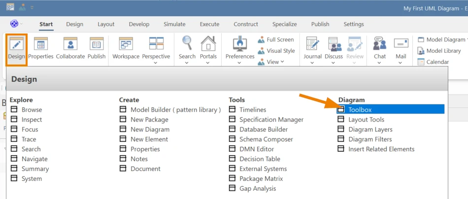
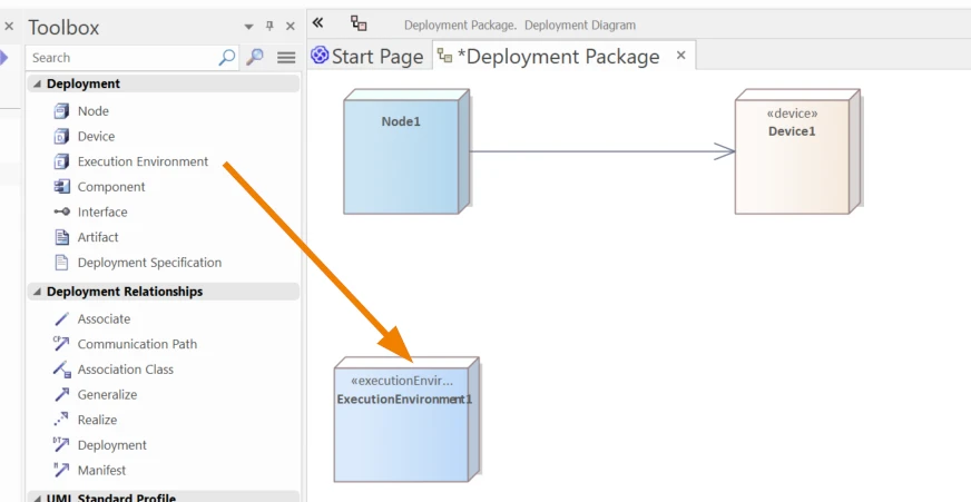
Tools like Sparx Systems Enterprise Architect make it easy to model this using ready-to-use deployment elements from the Diagram Toolbox.
UML Deployment Diagrams combined with Enterprise Architect’s capabilities benefit a variety of use cases. Some of the most notable ones are:
Illustrating the layout of nodes and artifacts makes system topology easy to communicate to stakeholders.
Helps plan for scalability and avoid bottlenecks by assigning components to hardware.
Serves as a shared reference across teams and can drive auto-generated deployment documents.
In Sparx EA you can update UML models from actual deployment or generate code from diagrams.
Spot single points of failure, plan redundancy, and visualize communication paths in advance.
To build a deployment diagram effectively, you need to understand the key elements and how they connect. Sparx Systems Enterprise Architect provides these elements in the Deployment Diagram toolbox, making it easier to model real-world infrastructure and execution environments.
| UML Element Type | Icon in EA Toolbox | Description |
|---|---|---|
| Node |

|
Node represents a physical piece of equipment, like a server or workstation, where the system is deployed. |
| Device |

|
Device is a physical electronic resource with processing capability where artifacts can be deployed and executed. |
| Execution Environment |

|
The Execution Environment element is type of node that offers an execution platform for specific components, which are deployed as executable artifacts. |
| Component |

|
A Component is a modular part of a system. Its behavior is defined by the interfaces it provides and requires. |
| Interface |

|
An Interface specifies a contract or set of behaviors that implementers agree to follow. |
| Artifact |

|
An Artifact represents any physical piece of information that the system uses or produces. |
| Deployment Specification |

|
A Deployment Specification outlines the parameters that guide how an artifact should be deployed. |
| UML Connector Type | Icon in EA Toolbox | Description |
|---|---|---|
| Association |
|
An Association Connector indicates a relationship between two model elements, often realized as an instance variable. |
| Communication Path |

|
Communication Path defines the channel through which two deployment targets can exchange signals and messages. |
| Association Class |
|
The Association Class allows an Association to carry its own attributes and operations. |
| Generalization |

|
Generalization represents inheritance between elements. |
| Realize |

|
Realization indicates that a source element implements or realizes a destination element. |
| Deployment |

|
Deployment is a type of dependency that shows an artifact being deployed onto a node or executable target. |
| Manifest |

|
The Manifest Connector indicates that the source artifact embodies the target model element. |
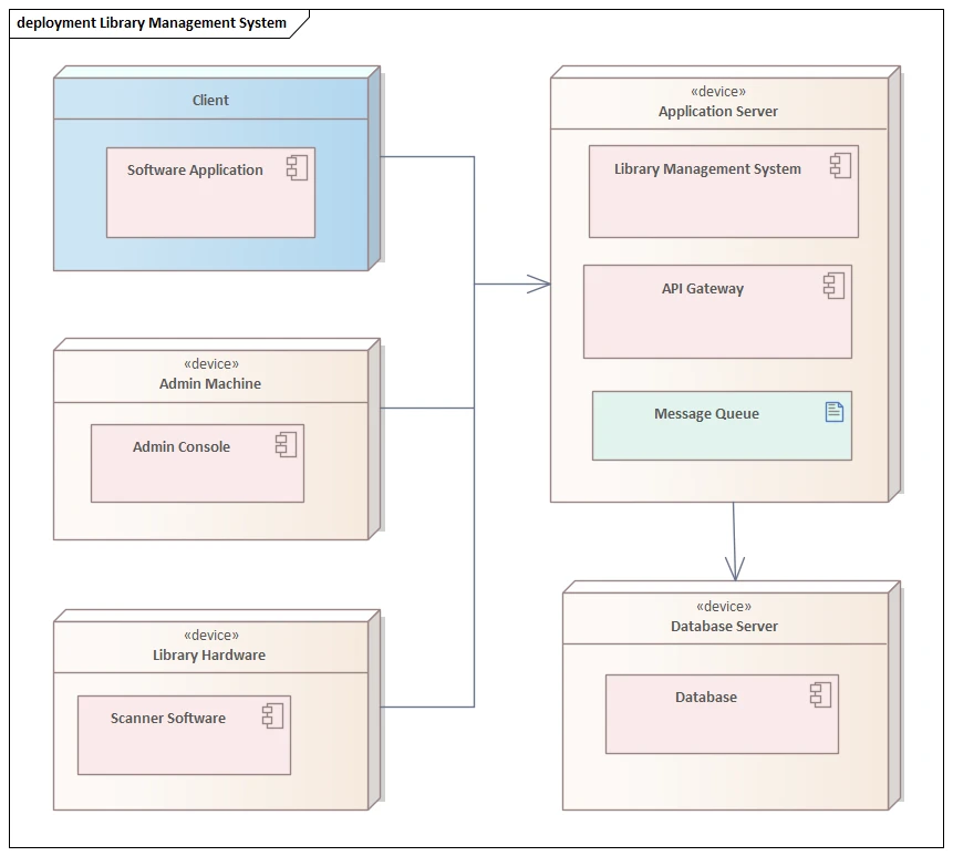
This deployment diagram shows how different parts of a Library Management System are distributed across physical machines. It’s modeled using Sparx Enterprise Architect and reflects a real-world setup.
On the client side, the user interacts with a software application. Admin tasks are handled on a separate admin machine running the console, while library hardware hosts scanner software for day-to-day operations. Each of these runs on its own device.
The application server takes on the core system workload. It runs three components:
These are deployed together but serve different purposes:
All three connect with a database server that stores the system’s data.
This diagram helps clarify not just what’s running, but where. It’s a practical way to align deployment decisions with architecture goals—whether you’re designing from scratch or mapping an existing setup.
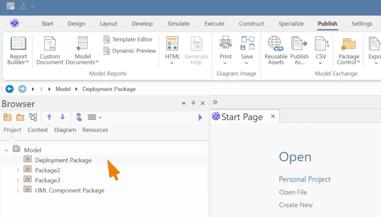
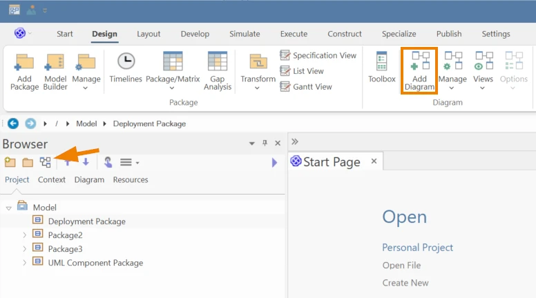
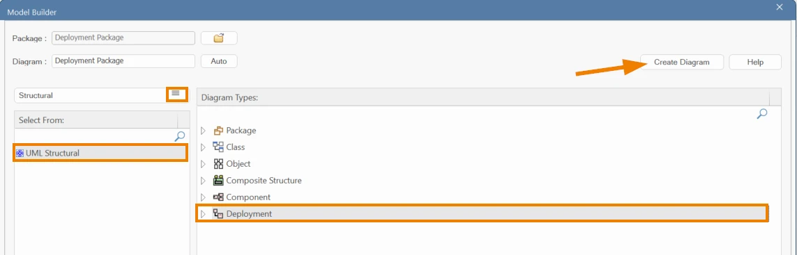
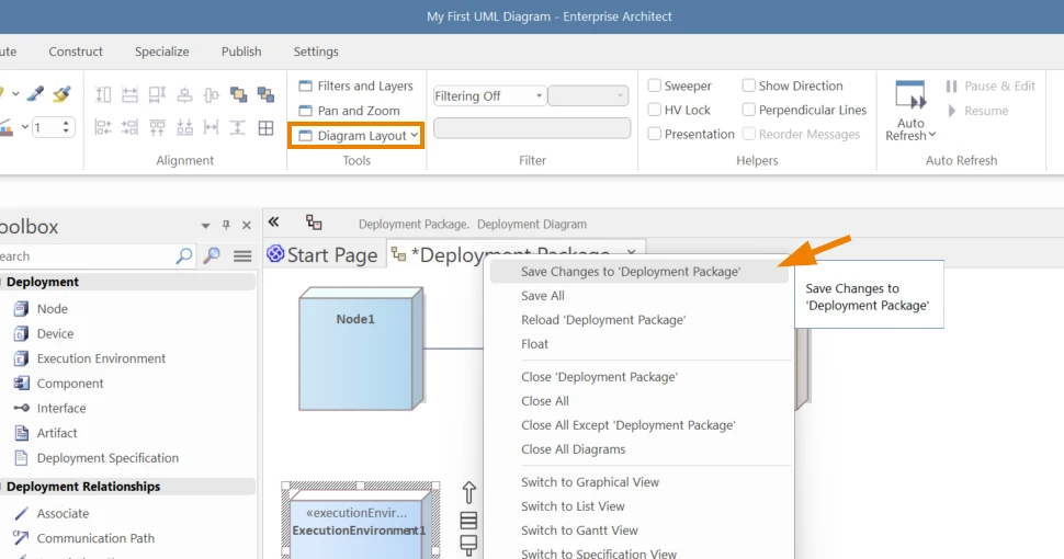
Follow these steps to create a UML Deployment Diagram using Sparx Systems Enterprise Architect:
Submit Your Request and We’ll Promptly Send a Payment link or Invoice.