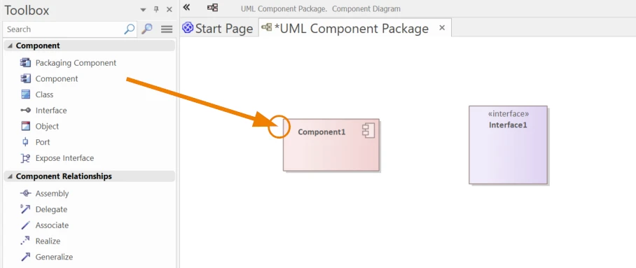
A UML Component Diagram shows how the system is broken down into independent entities called components. A software unit which could be installed in isolation with well-defined interfaces is a component; it will usually model much of the system such as a module, service, or external library.
While the Class Diagrams show the internal structure within the objects, the Component Diagrams focus on the top-level structure and how they all interrelate. You may view it as the top-down approach in the system where it indicates how the components will communicate through interfaces but hide the inner logic.
Component Diagrams are useful in developing modular applications, representing third-party integrations, or communicating architecture to stakeholders. Component Diagrams facilitate identifying clear responsibility and making systems more maintainable and extensible.
Component diagrams may seem technical at first sight but have useful applications in real projects. The following are five key benefits:
Component diagrams are the top-level “architecture map”, exposing system structure and inter-component dependencies—crucial for robust, scalable design.
They enable non-technical stakeholders to see how the pieces interconnect—by way of visual lollipops, sockets, and labeled interfaces.
Elements capture the behavior and can be replaced or reused if they have the same given/required interfaces, and design is plug‑and‑play.
By showing how the elements interrelate with classes, interfaces, and deployment elements, the diagrams enable traceability and maintenance.
Component diagrams are utilized by the software developers in the definition of implementation boundaries, distribution of skills, and module responsibility.
| UML Element Type | Icon in EA Toolbox | Description |
|---|---|---|
| Packaging Component |
|
Appears as a component but behaves as a package in the Browser window. |
| Component |

|
A system part structured through well-recognized interfaces; forms a unit to deploy. |
| Class |
|
A definition for objects which states structure and behaviour. |
| Interface |
|
A document describing the services offered by or demanded by a component. |
| Object |
|
A runtime instance of a class. |
| Port |
|
A formal interaction site between a component and the environment. |
| Expose Interface |
|
A graphical feature for the display of given or required interfaces of a class or a component. |
Connectors serve to illustrate structure, inheritance, implementation, and composition by describing the relationships between model elements.
| UML Connector Type | Icon in EA Toolbox | Description |
|---|---|---|
| Assembly |
|
Binds one component's required interface to a specified component's provided interface. |
| Delegate |
|
Maps the component's external ports to internal elements or interfaces. |
| Associate |
|
Refers to association, usually structured as instance variables within classes. |
| Realize |
|
Used to show one model element realizing the behavior of another. |
| Generalize |
|
Denotes inheritance among classes or components. |
This sample UML Component Diagram from Sparx EA shows the highest-level architecture for a bookstore order management system. Four central components exist: Product, Customer, Order, and Account.
Product and Customer both expose interfaces providing the product and customer data respectively. These interfaces are used by the Order component through assembly connectors, indicating the need for both components for transaction processing.
The Order component is the principal orchestrator. It will talk to the Product and Customer in order to get the necessary input and initiate the payment process.
Order element is dependent on a foreign Account element as well. A realization connector is applied in this case in order to indicate the account element fulfills the required Payment interface by Order.
The Account component offers a separate Account Details user interface in order to complete the transaction process.
This structure graphically illustrates how elements talk through required and provided interfaces with a focus on modularity, well-defined boundaries, and reuse—component-based architecture’s important objectives.
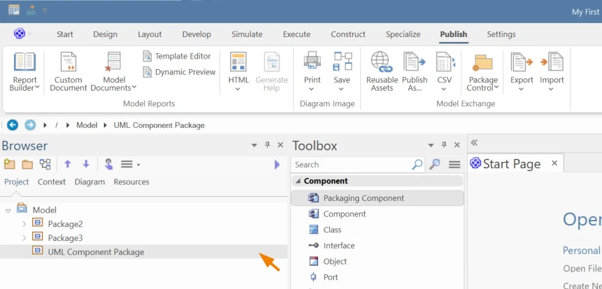
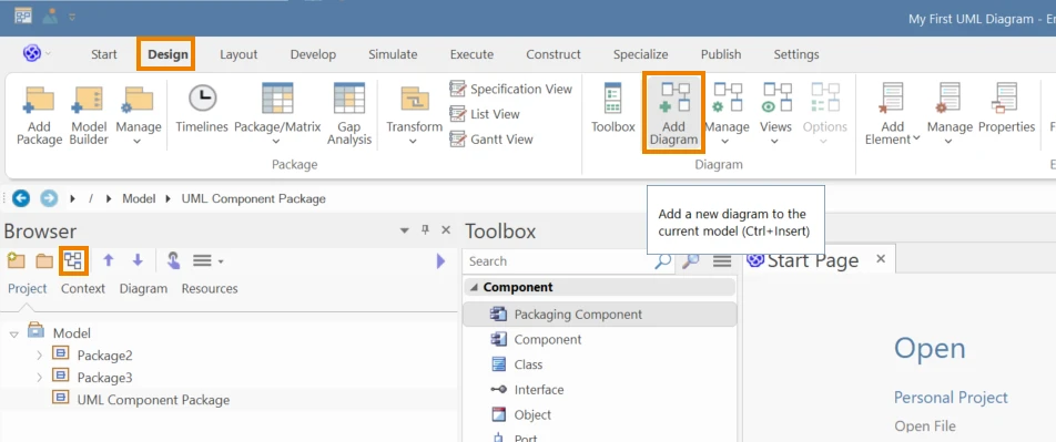
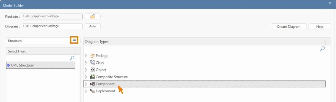
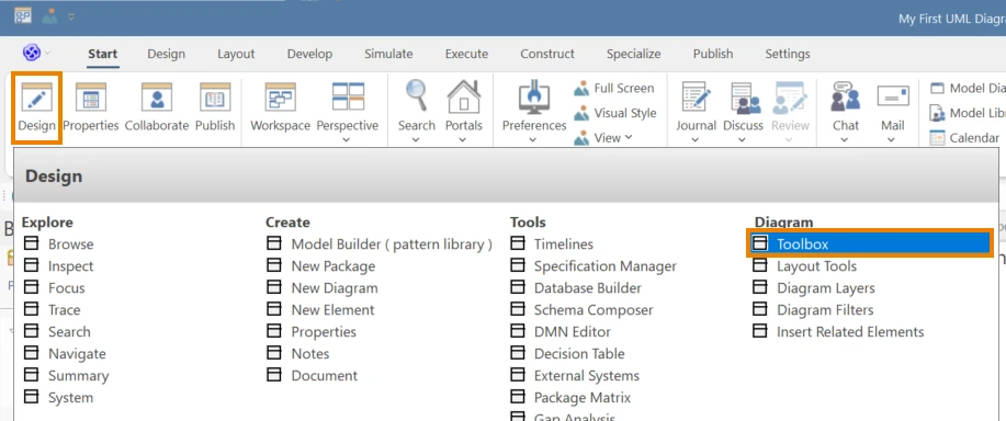
Use the following steps to define a UML Component Diagram in Sparx Systems Enterprise Architect:
Our consultants help you map, align, and modernize with customized Sparx EA consulting services—fast, focused, and aligned to your business goals.
Submit Your Request and We’ll Promptly Send a Payment link or Invoice.