
Understanding the difference between UML Sequence Diagrams and UML Communication Diagrams is fundamental skill in Sparx UML modeling. While both belong to the family of interaction diagrams, they emphasize very different aspects of system behavior. Choosing the right one at the right time can make your EA UML diagrams clearer, more maintainable, and more effective in communication with stakeholders.
In sparx uml modeling, analysts, architects, and developers often face the challenge of deciding which view best captures the story of their system. A sequence diagram is excellent for visualizing the step-by-step flow of messages over time, while a communication diagram helps highlight structural relationships and the overall message exchange pattern. Without understanding these differences, models risk becoming either too detailed for strategic communication or too abstract for technical validation. By mastering both views, teams can create Sparx UML models that balance clarity, precision, and traceability.
Kickstart your modeling in minutes. Build sequence and communication diagrams, validate flows, and share results fast.
What is a UML Sequence Diagram?

A Sequence Diagram shows how objects interact through messages over time. It represents elements as lifelines running vertically and uses arrows to illustrate synchronous, asynchronous, and return messages. Sequence diagrams make the order of communication explicit, making them a vital part of EA UML diagrams.
In Sparx UML modeling, sequence diagrams can include advanced constructs like combined fragments (alt, opt, loop), execution occurrences, and self-messages. They are particularly effective for modeling workflows, real-time systems, or service integrations where timing and order matter. By using Sparx Enterprise Architect sequence diagrams, teams can validate lifelines, message flows, and even reuse elements across diagrams for consistency.
What is a UML Communication Diagram?

A Communication Diagram focuses on the structural links between objects and the messages exchanged across those links. It shows objects connected by association lines, with messages numbered sequentially (1, 1.1, 1.2) to indicate order. This makes it compact, but less direct in showing exact timing.
In EA UML diagrams, communication diagrams are useful when you want to emphasize relationships over time sequence. They are excellent for quickly mapping how multiple components interact, such as in system integration or service-oriented architecture. With Sparx UML communication diagrams, architects can capture message flows while keeping the emphasis on structure, making them complementary to sequence diagrams.
Sequence vs Communication: Side-by-Side Comparison in Sparx UML Diagrams
| Aspect | UML Sequence Diagram | UML Communication Diagram |
|---|---|---|
| Focus | Highlights the time-ordered flow of messages, showing exactly when interactions occur. Useful for validating detailed business and system workflows. | Highlights structural relationships between objects, emphasizing how they connect and exchange messages rather than strict timing. |
| Notation | Uses lifelines running vertically with horizontal arrows for messages, combined fragments for conditions, and activation bars for execution. | Uses objects linked by connectors with numbered messages that indicate order, keeping the diagram compact and structural. |
| Strength | Provides clear visibility into the chronological order of operations, making it easy to trace complex processes step by step. | Provides a condensed view of all participating objects and their connections, simplifying large systems into a single overview. |
| Best For | Ideal for modeling dynamic behavior, detailed business processes, software protocols, or real-time interactions where order matters. | Ideal for illustrating static relationships, high-level integration mappings, or system overviews where clarity of connections is more important than timing. |
| Message Visibility | Explicitly shows synchronous, asynchronous, and return messages with clear visual indicators, easy for beginners to grasp. | Relies on message numbering schemes to communicate order, which can be less intuitive but remains effective for structural overviews. |
| Scalability | Vertical expansion makes large diagrams harder to fit on a page, though Sparx EA supports modularization and interaction references. | Maintains a compact structure even as the number of interactions grows, making it easier to present at executive or review meetings. |
| Learning Curve | Easier for beginners since the flow of time is intuitive, especially when validating step-by-step logic with stakeholders. | Slightly harder for newcomers because they must interpret numbering to understand sequence, though simple structures are quick to learn. |
| Use in Sparx UML Modeling | Rich support in Sparx Enterprise Architect, including combined fragments (alt/opt/loop), interaction overview links, and traceability. | Useful in EA for high-level architecture mapping, quick system snapshots, and complementing sequence diagrams with structural insights. |
When to Choose Which: Real Sparx UML Modeling Scenarios
Delete User Workflow with a Sparx UML Sequence Diagram

The first diagram illustrates a UML Sequence Diagram for a Delete User use case in a user management system. In Sparx Enterprise Architect, the Administrator lifeline initiates the process, triggering a boundary component that interacts with control logic and an account entity. The diagram shows message calls such as DeleteUser() and retrieveAccountDetails() in strict time order, including a reference to Close Account. This makes it highly effective in Sparx UML modeling when validating dynamic workflows, ensuring business rules are enforced, and providing developers and testers with precise chronological logic.
Delete User Workflow with a Communication Diagram
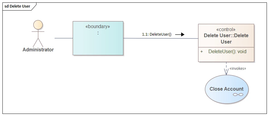
The second diagram models the same scenario as a UML Communication Diagram in EA UML diagrams. Rather than focusing on time sequence, it emphasizes the structural relationships: the Administrator, boundary, control, and account elements are connected with association links, and the numbered message 1: DeleteUser() indicates flow. In Sparx Enterprise Architect, this compact view helps architects and project managers quickly assess object collaboration and overall architecture. It highlights who communicates with whom, which is crucial for integration mapping and executive-level reviews.
Together, these examples show how Sparx Enterprise Architect enables you to reuse the same interaction logic across both diagram types, supporting Sparx UML modeling that balances technical validation with stakeholder communication. show how Sparx Enterprise Architect enables you to reuse the same interaction logic across both diagram types, providing clarity for both technical validation and high-level architecture communication.
Build Your UML Modeling Skills with instructor-led, hands-on courses from certified Sparx EA experts—tailored to your team and use cases.
Both diagrams belong in your Sparx UML modeling toolkit. Sequence diagrams give you clarity on “when” things happen, while communication diagrams help you see “who talks to whom.” Used together in Sparx Enterprise Architect, they provide a complete picture of system interactions.
FAQs on Interaction Diagrams in Sparx UML Models
1) Can I convert between uml sequence and communication diagrams in EA?
Yes. In Sparx Enterprise Architect, you can convert sequence and communication diagrams since both are based on the same interaction model. This ensures consistency and avoids duplication. Converting lets you switch between detailed chronological flows and compact structural views, giving stakeholders different perspectives while reusing the same model content effectively.
2) When should I use combined fragments (alt, opt, loop) in sequence diagrams?
Use combined fragments in Sparx UML sequence diagrams to represent variations in behavior. The alt fragment captures conditional paths, opt models optional actions, and loop defines repetitions. These constructs improve clarity, reduce ambiguity, and ensure that business rules and system logic are accurately captured, communicated, and validated across stakeholders and development teams.
3) How does message numbering work in communication diagrams?
Message numbering in UML communication diagrams ensures the reader understands order despite the structural focus. Messages are labeled sequentially (1, 1.1, 1.2), clarifying flow across connected objects. In Sparx Enterprise Architect, numbering automatically updates as you adjust messages, making it easier to maintain consistency while highlighting both relationships and communication sequence effectively within EA UML diagrams.
4) Can interaction overviews combine both views?
Yes. An Interaction Overview Diagram in Sparx UML modeling allows you to integrate both sequence and communication diagrams into a unified flow. It acts like a roadmap, referencing multiple interactions. This provides architects with a higher-level perspective, ensuring stakeholders understand how detailed message flows and structural interactions combine into a complete system behavior overview.


