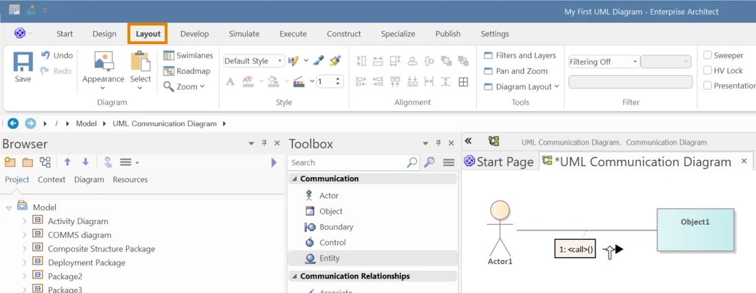
A UML Communication Diagram shows interactions between objects at run time, much like a Sequence Diagram, but from a link‑centric perspective. Messages are drawn on the connections between participants, and the focus is the collaboration structure rather than a left‑to‑right timeline. Ordering is expressed with hierarchical numbering (for example: 1, 1.1, 1.1.1, 1.2) to indicate call nesting and control flow. The result is a compact view that summarizes the same behavior a sequence diagram would show, while emphasizing who talks to whom.
In UML 2.x, the Communication Diagram replaces the UML 1.x Collaboration Diagram (which is distinct from the UML Collaboration metaclass). In Sparx Systems Enterprise Architect, you create one from the Communication pages of the Diagram Toolbox when you need a relationship‑first view of message exchange.
Communication diagrams help when you need a compact interaction view that emphasizes links and responsibilities over timeline layout. They complement sequence diagrams by preserving message order while making structure and coupling obvious.
Shows the same behavior as a sequence diagram but in less space, using numbered messages on links. Useful for presentations and quick reviews.
Exposes who talks to whom, through which links, so responsibilities and coupling are easy to see. Ideal when structure matters more than timing.
Nested numbering (1, 1.1, 1.1.1) captures call order and depth without a timeline. Teams can trace scenarios step by step with minimal notation.
Because links are explicit, you can spot unnecessary dependencies and plan interface changes. Small updates are easy to validate against the message paths.
Place objects near their components or nodes to relate interactions to architecture. Helpful in EA when reviewing runtime links alongside structure.
Show communication links and message exchanges effectively in Sparx Enterprise Architect. Explore Sparx EA Features
| Item | Image | Description |
|---|---|---|
| Actor |

|
An external entity (person, system, or organization) that interacts with the system. |
| Object |
|
A runtime instance of a Class that participates in the scenario shown on the diagram. |
| Boundary |

|
A stereotyped Object that represents a system boundary, typically a user‑interface screen or external interface. |
| Control |
|
A coordinator or manager element that directs flow, schedules work, or mediates between other participants |
| Entity |
|
A stereotyped Object that models a persistence or information store used by the system |
| Package |

|
A container used to organize the model; when placed on a diagram it can depict structural groupings and their relationships. |
| Connector | Image | Description |
|---|---|---|
| Associate |

|
Declares a relationship between two elements; commonly realized as a reference/attribute in one or both related Classes. |
| Nesting |

|
An alternative notation to show containment—one element is graphically nested within another to indicate ownership. |
| Realize |
|
Indicates that the source element implements or fulfills the contract of the destination element. |
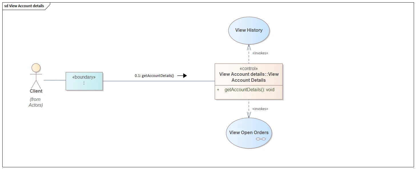
The diagram captures a single request to view account information in a link‑centric view. The Client (Actor) interacts with a «boundary» object that represents the UI. The boundary delegates to the **«control» **View Account Details, which coordinates the flow and exposes getAccountDetails(): void for traceability. A communication link from boundary to control carries the numbered message 0.1: getAccountDetails(), establishing order and leaving room for nested calls (e.g., 0.1.1). The control shows «invokes» dependencies to the View History and View Open Orders behaviors, indicating they can be triggered as part of the scenario.
Taken together, the single view makes responsibilities and coupling explicit: the client touches only the boundary; the boundary forwards to one coordinator; the coordinator calls supporting behaviors as needed. Hierarchical numbering preserves sequence without a timeline, while the explicit links reveal the runtime path at a glance and help reviewers confirm a clean separation of UI, orchestration, and use‑case logic.
Use the following steps to define a UML Communication Diagram in Sparx Systems Enterprise Architect:
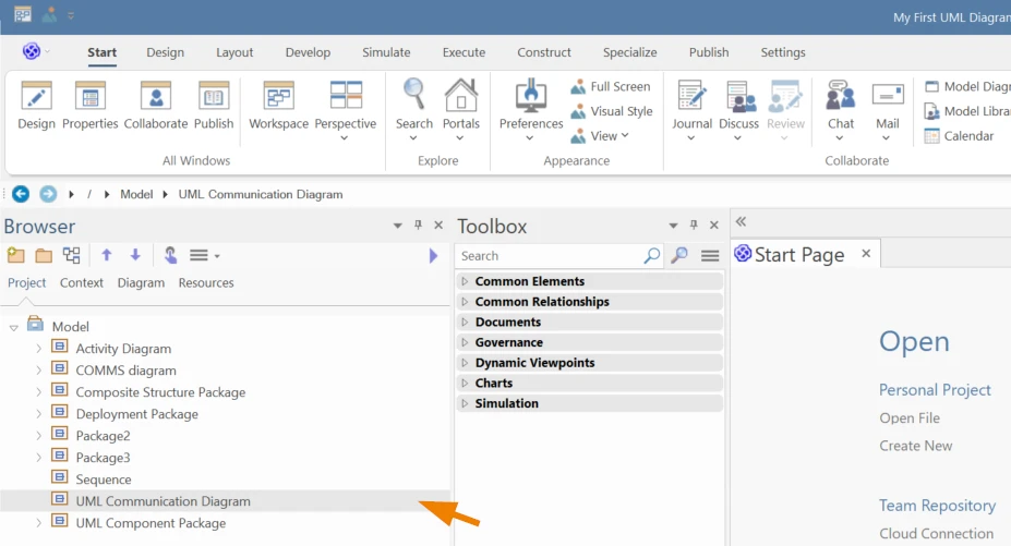
1. Select the Package in the Project Browser where the diagram should be created.
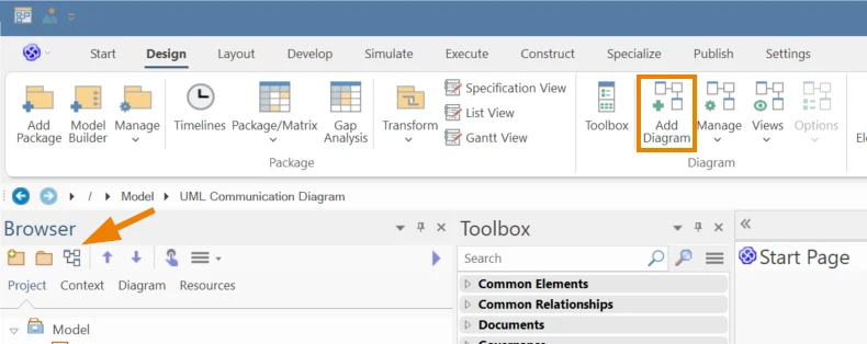
2. Go to Design > Diagram > Add Diagram, or click the Add Diagram icon above the Project Browser.
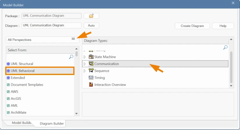
3. In the Diagram Builder, choose UML > Behavioral> Communication.
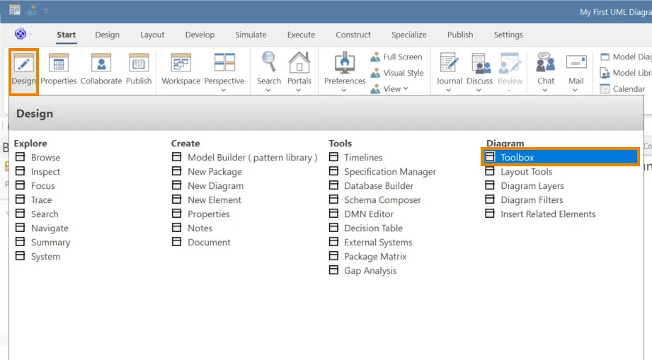
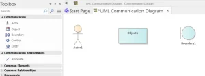
4. The Communication toolbox opens automatically; or enable it via Start > All Windows > Design > Diagram > Toolbox and load the Communication pages.
5. Add participants: Drag Actor, Object, Boundary, Control, and Entity as needed. For objects, use instance notation (e.g., :Boundary, cart:Cart).
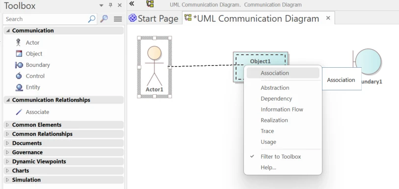
6. Create relationships: Draw Associations between participants to represent communication paths.
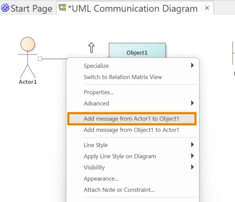
7. Add messages on relationships: right‑click a link and choose Add Message (<<Source>> to <<Destination>>) to create the call.
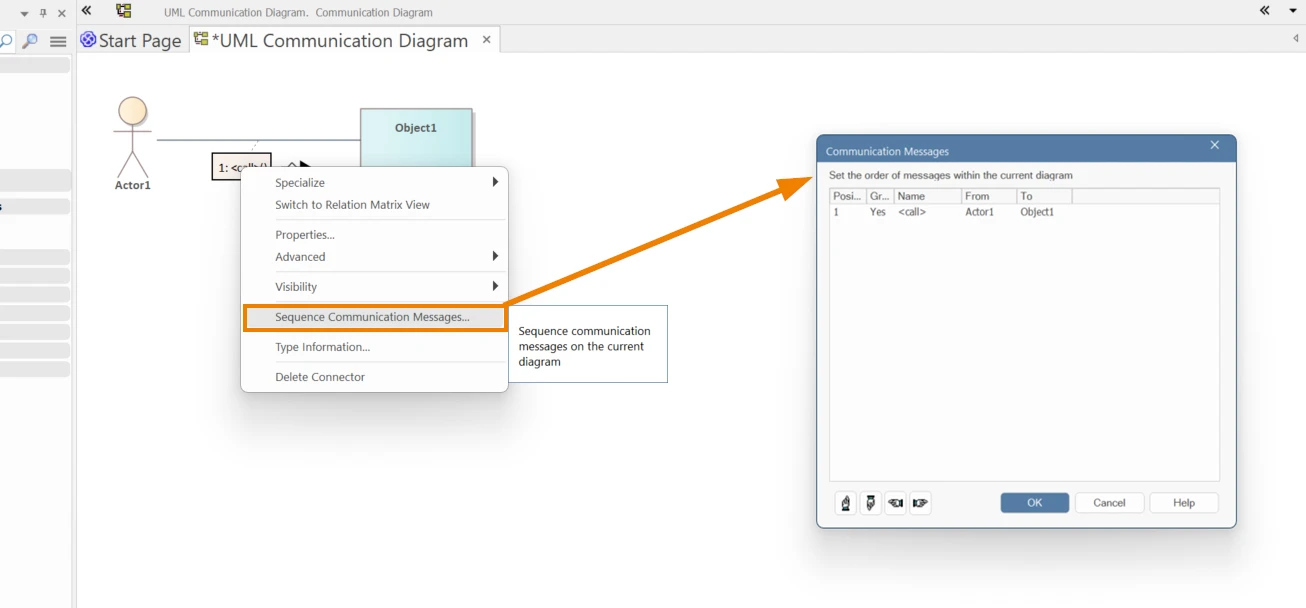
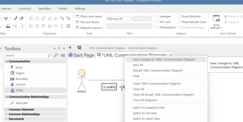
8. Ordering the messages: To set order, right‑click the message label > Sequence Communication messages (e.g., 1:<call>()) and edit the number before the colon (e.g., 1, 1.1, 1.1.1).
9. Label and arrange: keep labels readable; use Layout tools and align objects near the components or nodes they belong to.
10. Save (Ctrl+S) and review numbering for clarity before publishing the diagram.
When validated and refined, Sequence Diagrams becomes a reliable blueprint for development, integration, and testing. By ensuring accurate lifelines, clear message flows, and alignment with related models, you reduce ambiguity and bridge the gap between design intent and implementation reality.
Submit Your Request and We’ll Promptly Send a Payment link or Invoice.