If you need to capture what your system should do from a user’s perspective in Sparx Enterprise Architect, UML Use Case Diagrams are your starting point. They bridge the gap between business requirements and technical design, showing exactly what functionality your system needs to provide. In practice, actors and relations shape the use case diagram, while extension points indicate where extend behavior fits.
A UML Use Case Diagram is a standardized diagram in the Unified Modeling Language that depicts external actors and the goals they achieve through interactions with a system. It presents actors, use cases, and boundaries in one high‑level visual, making complex requirements easier to understand and communicate. Modelers often add generalization for actors or use cases to support specialization and specialisation where roles diverge.
Use Case Diagrams are widely used because they provide a bridge between business needs and system design. Use case diagrams are best applied at the early stages of a project when scope and stakeholder goals must be clarified. They help uncover external interfaces, align IT and business teams, and offer a lightweight visual anchor for requirements discussions. For business analysts, use case diagrams capture functional requirements; for architects, use case diagrams define system responsibilities; and for developers and testers, they create a foundation for scenarios, acceptance criteria, and traceability. Modelers often add generalization for actors or use cases to support specialization and specialisation where roles diverge.
Unlike Activity or Sequence Diagrams, Use Case Diagrams remain high-level. They show who interacts with the system and what goals they achieve, not the detailed steps or message flows. This distinction is important: while Activity Diagrams describe control flow and Sequence Diagrams map interactions step-by-step, Use Case Diagrams deliberately abstract away detail to emphasize scope and intent. Use case diagrams are most valuable at the boundary between business understanding and technical specification, where simplicity and clarity are critical. Modelers often add generalization for actors or use cases to support specialization and specialisation where roles diverge.
In Enterprise Architect, these diagrams become actionable—linking to structured scenarios, requirements, and test cases for end‑to‑end modeling and governance. This makes them useful to anyone modeling requirements in EA, from new users learning UML basics to experienced modelers seeking a refresher on best practices. Modelers often add generalization for actors or use cases to support specialization and specialisation where roles diverge.
Whether you’re a beginner or an advanced modeler, our guided sessions help you build confidence and mastery with UML diagrams in Enterprise Architect.
Use Case Diagrams offer a wide range of advantages in systems analysis and design. The points below highlight only some of the most important benefits, while in practice organizations may realize many more depending on their domain, processes, and tool usage. Modelers often add generalization for actors or use cases to support specialization and specialisation where roles diverge.
A UML Use Case Diagram makes it easy to visualize what is inside the system boundary and what lies outside. This early clarity helps project teams agree on responsibilities and prevent scope creep. Modelers often add generalization for actors or use cases to support specialization and specialisation where roles diverge.
Use Case Diagrams provide a simple language for both technical and non‑technical stakeholders. They are easy to read, which makes them effective tools for workshops and requirements discussions. In practice, actors and relations shape the use case diagram, while extension points indicate where extend behavior fits.
Each use case in a UML Use Case Diagram can map directly to development tasks and test cases. This linkage ensures coverage of functional requirements across the lifecycle. In practice, actors and relations shape the use case diagram, while extension points indicate where extend behavior fits.
Use Case Diagrams work well in agile settings where scope is defined and refined in increments. They act as a living artifact that can evolve with each iteration. Modelers often add generalization for actors or use cases to support specialization and specialisation where roles diverge.
When modeled in Enterprise Architect, use case diagrams connect seamlessly with requirements, components, and test cases. This end‑to‑end traceability strengthens governance and compliance. To avoid ambiguity, use case descriptions state preconditions and postconditions explicitly, guiding scenarios across the system boundary.
Understanding the fundamental elements of a UML Use Case Diagram is essential for accurate modeling. These core concepts — drawn from the OMG specification and Sparx Systems’ guidance — clarify how actors, use cases, boundaries, and relationships define scope and responsibilities. Together use case diagram ensure your diagram is both compliant and practical. To avoid ambiguity, use case descriptions state preconditions and postconditions explicitly, guiding scenarios across the system boundary.
An Actor represents a role played by a user, another system, a machine, or even a subsystem that interacts with the subject system from outside its boundary. Actors are not individuals but roles — a single entity can play multiple actors, and an actor can be played by multiple entities.
According to the OMG UML specification (v2.5.1), an Actor models the type of role interacting with Use Cases, exchanging signals or data. In practice, actors may use the system via interfaces like GUIs, batch processes, or APIs. Actors initiate or participate in Use Cases, and their interactions are further described in Use Case scenarios. In EA, actors can also appear in Sequence Diagrams, displayed in rectangle notation. Teams align on a use case by mapping actor goals, detailing relations, and recording scenarios in concise descriptions.
A Use Case describes how an actor interacts with the system to achieve a discrete unit of work. It must leave the system in a complete state — either successfully executed or rolled back. Each use case usually has requirements and constraints that define its behavior, and scenarios that explain workflows over time, including alternate or exception flows. Use Cases may be illustrated with Sequence Diagrams and extended with Extension Points. In EA, Use Cases can also appear as specialized types such as Business Use Case or Test Case. A Use Case specifies observable results of value to one or more actors or stakeholders. Teams align on a use case by mapping actor goals, detailing relations, and recording scenarios in concise descriptions.
A System Boundary is a non‑UML element that visually encloses the use cases belonging to a subject system, clarifying scope. It distinguishes internal system functionality from external actors. OMG’s UML spec notes that the subject can be shown as a rectangle with use cases inside it. In EA, the System Boundary can be styled with swimlanes, border options, and custom shapes, aiding in grouping related elements. Boundaries are associated with classifiers such as Classes, Components, or Subsystems, reinforcing the distinction between what the system owns and what external actors access. Teams align on a use case by mapping actor goals, detailing relations, and recording scenarios in concise descriptions.
Relationships connect actors and use cases, indicating how users achieve goals. This use case clarifies how each actor engages within the system boundary; include is used for shared steps and extend for optional flows.
An Association shows communication between an actor and a use case. It may define roles, multiplicity, and constraints. OMG specifies it as a semantic relationship between instances, enabling links between conforming elements. Associations are the most basic connector in a use case diagram. In practice, actors and relations shape the use case diagram, while extension points indicate where extend behavior fits.
An Include relationship indicates that one use case always incorporates the behavior of another. It extracts common mandatory behavior, avoiding duplication across multiple use cases. The OMG spec (v2.5.1, p.641) defines Include as inserting the behavior of the included use case into the base use case. The base use case depends on the included behavior, which is always executed at a defined location. Modelers often add generalization for actors or use cases to support specialization and specialisation where roles diverge.
An Extend relationship adds optional or conditional behavior to a base use case at defined extension points. The OMG spec notes that Extend specifies how and when additional behavior may augment the base use case. The extended use case is meaningful by itself; the extending use case adds modular behavior triggered only under specific conditions. Each use case diagram connects actors to goals; relations, include, and extend keep scenarios consistent at key extension points.
A Generalization shows inheritance between actors or between use cases. The specific classifier inherits the features of the general classifier. For actors, generalization allows specialization (e.g., Customer → VIP Customer). For use cases, it creates a taxonomy where specialized behaviors refine general ones. Each use case diagram connects actors to goals; relations, include, and extend keep scenarios consistent at key extension points.
Extension Points are named hooks inside a base use case where extensions may apply. They identify precise points in the behavior flow where optional scenarios can be inserted. A use case can have multiple extension points, each allowing for different extending behaviors or conditional application. Teams align on a use case by mapping actor goals, detailing relations, and recording scenarios in concise descriptions.
Beyond diagrams, Use Case Descriptions provide detailed text documenting preconditions, main flows, alternate flows, and postconditions. These descriptions ensure completeness, supporting requirements and test coverage. In EA, scenarios and notes capture this information directly within the model, linking diagrams to structured documentation. Teams align on a use case by mapping actor goals, detailing relations, and recording scenarios in concise descriptions.
A scenario describes the detailed sequence of steps through which an actor and the system interact to accomplish a goal. While the UML Use Case Diagram provides a structural overview, scenarios give the narrative context — the actual workflow. Scenarios illustrate how the system responds to actor inputs, including normal and exceptional conditions. This use case clarifies how each actor engages within the system boundary; include is used for shared steps and extend for optional flows.
In Enterprise Architect, scenarios are managed in the Scenarios tab, allowing teams to capture textual steps that can later be transformed into Activity or Sequence Diagrams for visualization. This integration ensures both clarity for stakeholders and traceability within the modeling environment. In practice, actors and relations shape the use case diagram, while extension points indicate where extend behavior fits.
Preconditions define what must be true before a use case begins, such as a user being authenticated or a required resource being available. Postconditions guarantee the state of the system once the use case is complete, ensuring consistency whether the interaction succeeds or fails. In practice, actors and relations shape the use case diagram, while extension points indicate where extend behavior fits.
According to UML standards and Sparx documentation, preconditions and postconditions act as constraints that frame the scope of a use case. In EA, these can be added directly in the use case’s properties or through constraint fields, making them visible in reports and ensuring downstream stakeholders know the assumptions and guarantees tied to each use case. Each use case diagram connects actors to goals; relations, include, and extend keep scenarios consistent at key extension points.
The main flow represents the primary success path, showing the steps that lead from initiation to the intended outcome without deviations. Alternate flows describe variations, exceptions, or error handling paths that branch from the main sequence. Both are vital to complete requirements coverage. Main and alternate flows help ensure that the model reflects not only ideal operations but also real-world contingencies. Each use case diagram connects actors to goals; relations, include, and extend keep scenarios consistent at key extension points.
Enterprise Architect supports structured scenario editing where each flow can be captured separately, labeled, and linked to test cases. This approach enables systematic validation that all possible paths have been considered and documented. Each use case diagram connects actors to goals; relations, include, and extend keep scenarios consistent at key extension points.
Documentation transforms diagrams and scenarios into reusable assets for the wider team. In EA, you can enrich each use case with scenario steps, constraints, and notes. Structured specifications allow preconditions, triggers, flows, and postconditions to be recorded in detail. These narratives can be linked to requirements, test cases, and even generated into formal reports or web-based outputs for stakeholder review. In practice, actors and relations shape the use case diagram, while extension points indicate where extend behavior fits.
EA also allows exporting to documents or publishing to Prolaborate for collaborative access. This ensures that use case scenarios and documentation are not isolated artifacts but part of an integrated repository that supports governance, compliance, and ongoing project communication. This use case clarifies how each actor engages within the system boundary; include is used for shared steps and extend for optional flows.
| UML Element Type | Item | Description |
|---|---|---|
| Actor |

|
An external entity (person, system, or organization) that interacts with the system. |
| Use Case |

|
Describes a functional interaction or goal that the system provides to an actor. |
| Test Case |

|
Represents a set of conditions or inputs to verify a use case's correct behavior. |
| Collaboration |

|
Defines an interaction between roles or elements working together to achieve a goal. |
| Collaboration Use |

|
Shows a specific way a collaboration is applied to achieve a desired result. |
| Boundary |

|
Represents the interface between the system and its actors (often as a system box). |
| Package |
|
Groups related elements together to organize the model. |
| UML Connector Type | Connector | Description |
|---|---|---|
| Use |
|
Represents that an element uses the functionality of another. |
| Associate |

|
Links an actor to a use case, showing interaction or communication. |
| Generalize |

|
Represents inheritance between actors or between use cases. |
| Include |

|
Indicates that one use case always incorporates another's behavior. |
| Extend |

|
Shows optional or conditional additional behavior to a base use case. |
| Realize |

|
Shows that a classifier implements a contract defined by another element (e.g., interface). |
| Invlokes |

|
Depicts one behavior explicitly triggering another. |
| Precedes |

|
Indicates that one behavior must occur before another in sequence. |
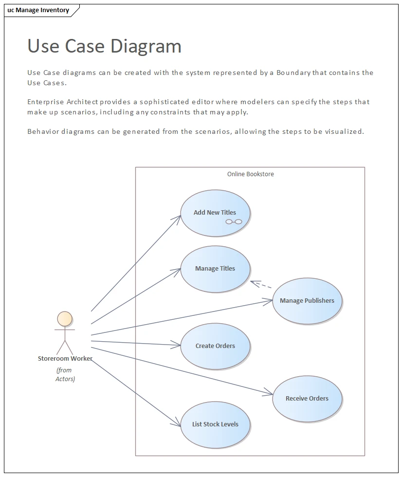
The Storeroom Worker (primary actor) maintains the bookstore’s catalog and stock within the Online Bookstore system boundary. Key goals are: Add New Titles, Manage Titles, Manage Publishers, Create Orders, Receive Orders, and List Stock Levels. This use case clarifies how each actor engages within the system boundary; include is used for shared steps and extend for optional flows.
A1) Publisher missing: during Add New Titles, the worker opens Manage Publishers to create/update the publisher, then resumes the add‑title step.
A2) Damaged or short shipment: during Receive Orders, the worker flags discrepancies; system creates a pending adjustment for finance and marks items as quarantined.
E1) Invalid metadata: Manage Titles rejects incomplete or malformed fields; worker corrects and retries. Teams align on a use case by mapping actor goals, detailing relations, and recording scenarios in concise descriptions.
Pre: Worker is authenticated; required supplier/publisher data exists or can be added; user has permissions to create orders.
Post: Catalog entries are consistent; orders placed (or updated); stock levels reflect received quantities; audit trail updated. Teams align on a use case by mapping actor goals, detailing relations, and recording scenarios in concise descriptions.
Capture the narrative under the Scenarios tab of each use case (Main, Alternate). Add constraints for preconditions/postconditions, and generate a Sequence Diagram from the scenario to visualize steps. Modelers often add generalization for actors or use cases to support specialization and specialisation where roles diverge.
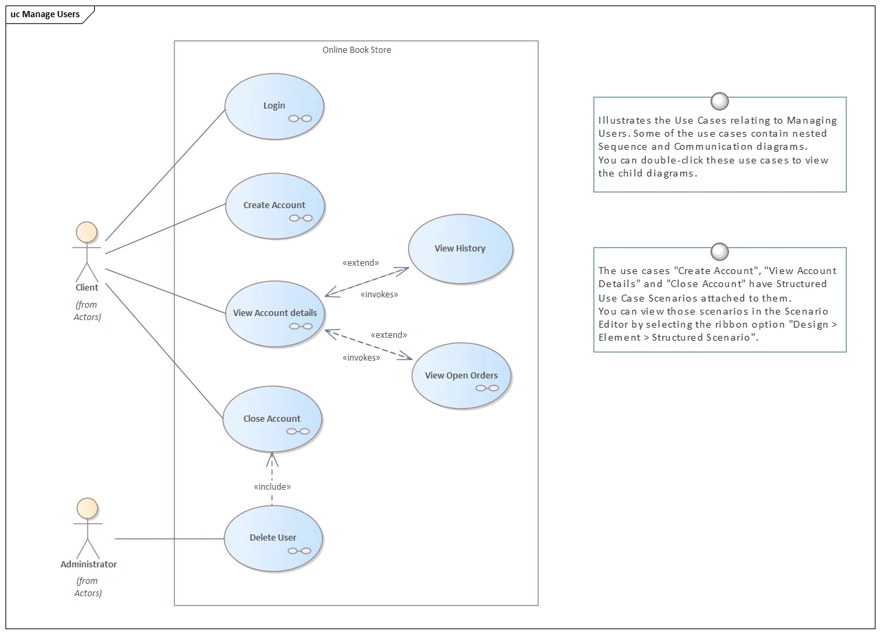
The Client and Administrator interact with the Online Book Store to manage accounts and review order history. Use cases include Login, Create Account, View Account details, Close Account, Delete User (admin), View History, and View Open Orders. Each use case diagram connects actors to goals; relations, include, and extend keep scenarios consistent at key extension points.
A1) Forgotten credentials: before Login, client initiates recovery; after reset, resumes the main scenario. Well-written use case descriptions capture preconditions and postconditions, and scenarios document the narrative.
A2) Profile update needed: from View Account details, client edits attributes then returns to viewing history. Modelers often add generalization for actors or use cases to support specialization and specialisation where roles diverge.
E1) Close Account blocked: open obligations (e.g., unpaid balance) prevent closure; system explains conditions and points to View Open Orders to resolve. Each use case diagram connects actors to goals; relations, include, and extend keep scenarios consistent at key extension points.
E2) Compliance purge: admin executes Delete User when retention conditions apply. To avoid ambiguity, use case descriptions state preconditions and postconditions explicitly, guiding scenarios across the system boundary.
Pre: For protected data, Login has succeeded; client owns the account; admin has deletion rights. Where behaviors vary, generalization supports specialization; at defined extension points you can extend the base use case.
Post: Account state reflects requested operations; audit events recorded; historic orders remain according to retention policy. Teams align on a use case by mapping actor goals, detailing relations, and recording scenarios in concise descriptions.
Define Extension Points on View Account details (e.g., after‑profile‑load) and connect View History/View Open Orders with Extend, setting the condition (user chooses that option). In Close Account, add constraints (e.g., no pending payments). Publish the model so stakeholders can click through from the use case to its scenarios. Modelers often add generalization for actors or use cases to support specialization and specialisation where roles diverge.
A Use Case Diagram summarizes user goals and relations, while a User Story captures narrative steps. Use Case descriptions specify preconditions and postconditions, ensuring clarity. Together, they guide scenarios across the system boundary, avoiding ambiguity and aligning stakeholders on required outcomes.
Yes. An actor can represent an external system, service, or hardware. For example, a Payment Gateway may serve as an actor. Where behaviors differ, generalization enables specialization. Extension points let modelers show optional flows, while actors consistently define roles external to the system boundary.
Use Include for mandatory shared actions reused by multiple use cases. Extend is used for optional or conditional behavior, linked at extension points. Mapping actor goals, detailing relations, and documenting scenarios ensures consistent understanding. Teams align on requirements by applying Include and Extend appropriately within diagrams.
In Enterprise Architect, open the Scenarios tab of a use case. Add Alternate or Exception flows to document variations. These flows clarify actor interactions across the system boundary. Include is applied to shared steps, while Extend supports conditional behavior, making alternate flows explicit and traceable within models.
Yes, but apply it sparingly. Generalization models inheritance between use cases or actors. Prefer Include or Extend for sharing behavior. Generalization is useful when a child is a strict specialization of a parent. Actors, relations, and extension points frame when and where such specialization appropriately applies.
UML Use Case Diagrams serve as a powerful tool for capturing and communicating system functionality from a user’s perspective. Whether you’re engaging stakeholders, defining requirements, or laying the foundation for more detailed analysis, use case diagrams offer a clear and intuitive starting point.
By using modeling tools like Sparx Enterprise Architect, you can enhance these diagrams with structured scenarios, nested behavior diagrams, and collaboration features, making your models not just informative, but actionable.
Submit Your Request and We’ll Promptly Send a Payment link or Invoice.