UML State Machine Diagram with Enterprise Architect

What is a UML State Machine Diagram?

A State Machine Diagram in UML is a behavioral diagram that shows the sequence of states an object goes through during its lifetime in response to events.

State Machine representations in UML are based on the Harel State Chart Notation and therefore are sometimes referred to as State Charts.

When designing software systems, it’s often important to model how an object behaves over time and how it changes in response to events.

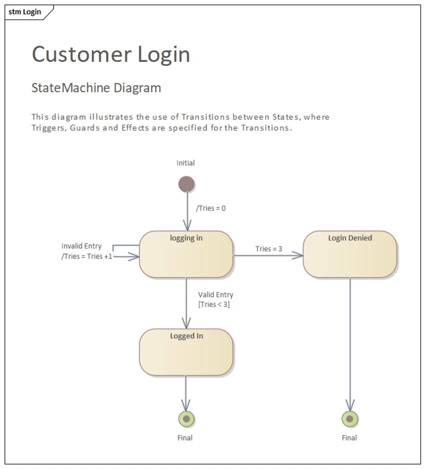
It shows states, transitions, triggers, and actions – how an object reacts to internal or external events during its lifetime.

Why use UML State Machine Diagrams?

State Machine diagrams excel at modeling systems with clear operational modes, such as user interfaces (login states, navigation flows), embedded systems (device operational states), business processes (order processing workflows), and protocol implementations (connection states in networking).

They’re particularly valuable for systems where the response to an event depends heavily on the current state, helping developers understand complex behavioral logic and identify potential issues like unreachable states or missing transitions.

Key Concepts in UML State Machine Diagrams

Guard Conditions

Boolean expressions in square braces [] that must be True for a transition to be triggered. In the above example, a customer login must be successful in less than 3 attempts [Tries < 3], if not, the system login will be denied.

Actions

Actions can occur during transitions or within states. Transition actions execute when the transition fires, while state actions include entry, exit, and do activities.

Hierarchical States

Hierarchical States allow states to contain other states, creating nested state machines. This enables modeling complex behaviors where substates inherit transitions from their parent states.

Concurrent States

This represent situations where an object can be in multiple states simultaneously, shown using dashed lines to separate concurrent regions.

Start Your Training Journey Today!

Access our Beginner-friendly UML courses and step confidently into advanced Topics.

Basic Elements and Relationships in a UML State Machine Diagram

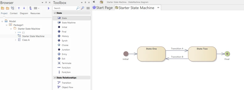
State Machine Diagram Toolbox Icons in Sparx EA

UML Element Type Icon in EA Toolbox Description
State state element in uml state machine toolbox ea Represented by a rounded rectangle containing the state name. This is the fundamental building block where objects exhibit specific behavior or wait for events.
State Machine state machine element in sparx ea uml state machine diagram A State Machine element acts as a container for groups of related State elements.
Initial initial element in sparx systems uml state machine toolbox A filled black circle marking where the state machine begins execution. Each state machine must have exactly one initial state.
Final final element in sparx uml state machine diagram toolbox A circle containing a filled black circle, indicating successful completion or termination of the state machine.
History history element in ea uml state machine diagram Shallow and Deep history are indicators that remember the last active substate when re-entering a composite state.
Synch synch element in enterprise architect uml state machine diagram toolbox A Synch state is useful for indicating that concurrent paths of a State Machine are synchronized. They are used to split and rejoin periods of parallel processing.
Object object element in ea uml state machine diagram toolbox An Object is a particular instance of a Class at run time.
Choice datatype element in uml ea tool A diamond shape representing a decision point where the transition path depends on guard conditions being evaluated.
Junction datatype element in uml ea tool A filled black circle used to merge or split transition paths, helping to simplify complex transition logic.
Entry datatype element in uml ea tool A small circle on the border of a composite state, providing a controlled entry mechanism into the state.
Exit datatype element in uml ea tool A circle with an X, offering a defined exit mechanism from composite states.
Terminate datatype element in uml ea tool An X symbol indicating abrupt termination of the state machine execution.
Fork/Join datatype element in uml ea tool
  • Fork splits a single flow into a number of concurrent paths
  • Join merges a number of concurrent flows back into a single flow
  • State Machine Diagram Connectors and Relationships

    UML Connector Type Icon in EA Toolbox Description
    Transition uml associate connector States that a stereotype extends a UML metaclass (the «extends» relationship).
    Object Flow uml generalization connector Indicates inheritance between stereotypes so the child stereotype inherits the parent’s tags and rules.

    How to create State Machine Diagrams in Sparx Enterprise Architect?

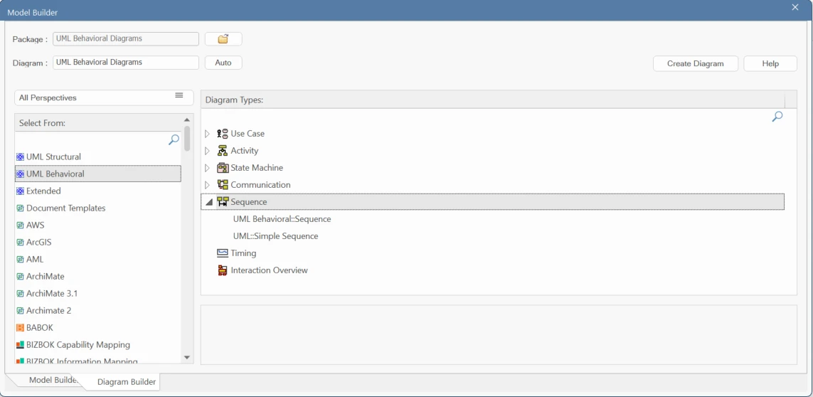
    • To create a new State Machine diagram, select Start > Design > Create > New Diagram, then UML Behavioral > State Machine. It lists all the model perspectives available in Enterprise Architect.
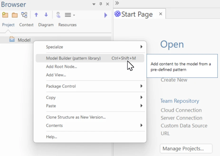
    • To start with a template, right click on the root package and select Model Builder or (Ctrl + Shift + M).
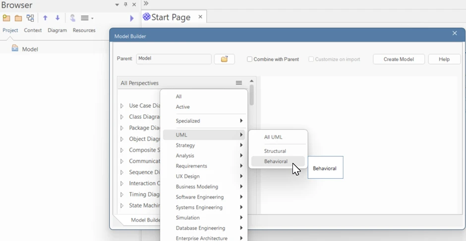
    • From the perspectives, choose UML → Behavioral diagrams.
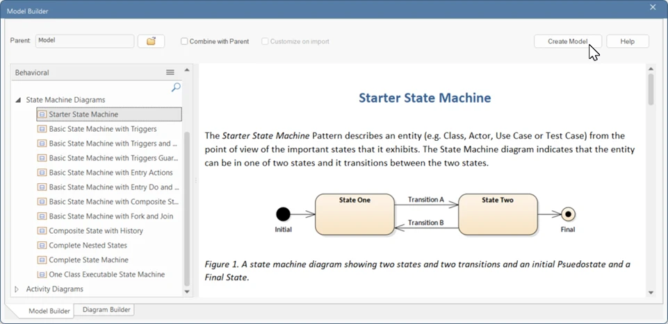
    • Under Behavioral diagrams, drop down State Machine Diagrams and select the required pattern from the list.
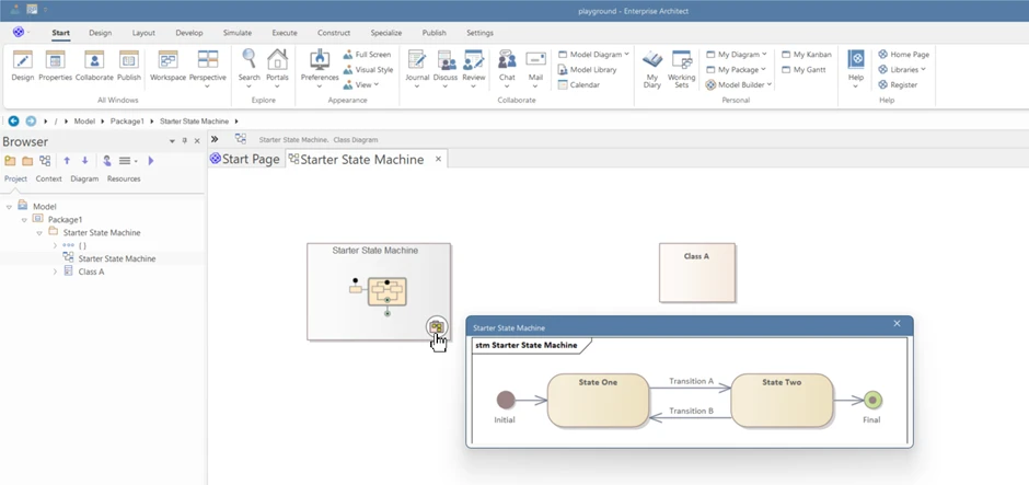
    • Click on Create Model to get started with a base State Machine template. The resulting model is as follows;
    • Double-click the Starter State Machine to open the State Machine Diagram within.

    Accelerate your Sparx EA Implementation much Faster with our Expert

    Get Sparx Systems Enterprise Architect and begin creating powerful UML package diagrams with ease. Buy EA Now!

    Learn More