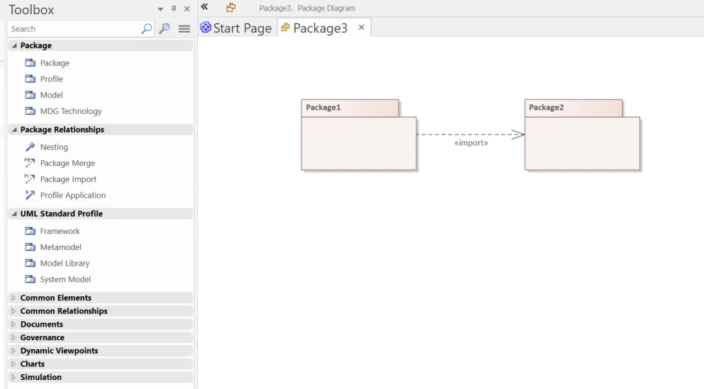
A UML Package Diagram is a powerful structural view that organizes related model items like classes, use cases, or even entire diagrams into packages, clearly mapping out how these packages depend on or extend one another. These diagrams play a key role in simplifying complex systems, making them easier to manage and understand. Tools like Sparx Systems Enterprise Architect make it easier to create and maintain UML package diagrams using the Package elements and their connectors directly from the Diagram Toolbox.
At its core, a package is a named namespace. Everything placed inside it must have unique names, and while a model element may be referenced from many packages, it can belong to exactly one home package. Packages themselves can nest inside one another, creating a clean, hierarchical structure ideal for modularization. This type of diagram package view is essential in both small-scale and enterprise-level modeling.
Using package diagram UML models, you can:
This makes UML package diagrams especially valuable when you’re dealing with large, complex models where clarity and maintainability are key. In addition, these diagrams help communicate your system’s structure to stakeholders, developers, and business analysts alike.
Get Sparx Systems Enterprise Architect and begin creating powerful UML package diagrams with ease. Buy EA Now!
| UML Element Type | Icon in EA Toolbox | Description |
|---|---|---|
| Package |
|
Used to organize your project contents. When added onto a UML package diagram, it depicts the structure and relationships of your model. |
| Profile |
|
Generates a Profile Package with the stereotype «profile», used to define new types of structure in a model. |
| Model |
|
Generates a Model Package with the stereotype «model», representing the parent node in a model structure. |
| UML Connector Type | Icon in EA Toolbox | Description |
|---|---|---|
| Nesting |
|
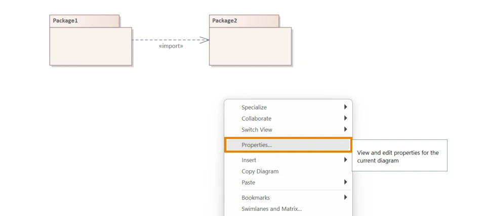
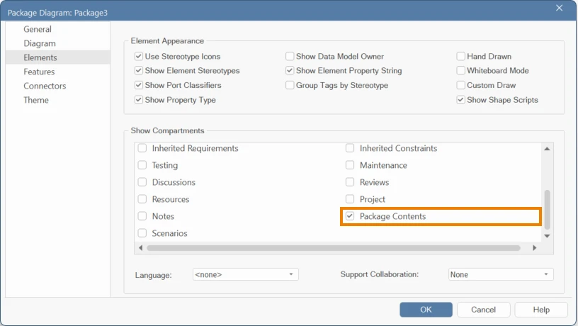
An alternative graphical notation for showing containment of elements. Reflects internal structure; contents can be displayed by enabling 'Package Contents' in diagram properties. |
| Package Merge |
|
Shows that the contents of the target Package are merged into the source Package. Existing elements in the source may be expanded by those in the target. |
| Package Import |
|
Indicates that the source Package has access to elements from the target Package. The source's namespace is extended, while the target remains unaffected. |
| Profile Application |
|
Indicates that a Profile has been applied to a Package, influencing its modeling semantics. |
| UML Connector Type | Icon in EA Toolbox | Stereotype | Description |
|---|---|---|---|
| Framework |
|
«framework» | Represents the parent node in a framework structure. |
| Metamodel |
|
«metamodel» | Represents the parent node in a metamodel structure. |
| Model Library |
|
«modelLibrary» | Represents the parent node in a model library structure. |
| System Model |
|
«systemModel» | Represents the parent node in a system model structure. |
Accelerate your team’s modeling skills with our expert-led UML and Sparx EA training programs.
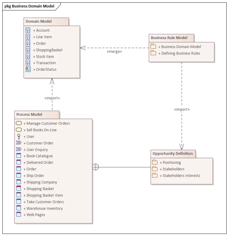
The diagram below illustrates a simplified Online Bookstore system using a UML package diagram example in Enterprise Architect. Each package groups relevant elements based on functionality or concern:
To illustrate real-world relationships:
This UML package diagram explanation demonstrates how diagrams can break down a complex system into understandable, structured views—connecting abstract rules, technical models, and business priorities within a single visual model.
Follow these steps to create your own UML package diagram using Sparx Systems Enterprise Architect:
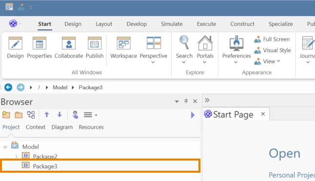
1. In the Project Browser, select the package where you want to create the diagram.
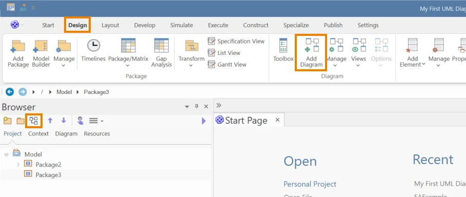
2. Click on the Add Diagram icon in the Project Browser, or go to Design > Diagram > Add Diagram from the ribbon menu.
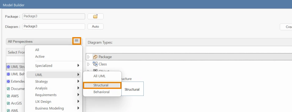
3. In the Diagram Builder, click on the Perspective icon → select UML > Structural and choose Package Diagram.
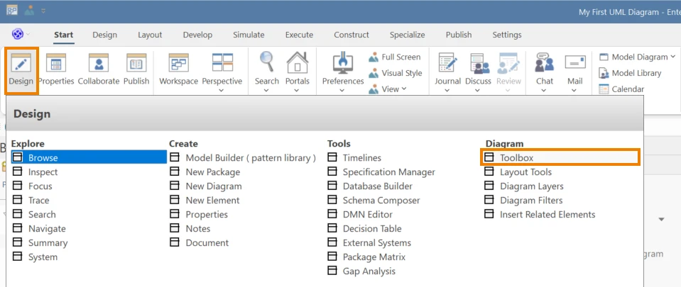
4. EA will show the related toolbox automatically. If not, go to Start > All Windows > Design to enable the toolbox.
5. From the toolbox, drag and drop elements like Package, Model Library, and Profiles onto the diagram. Add connectors (like Import, Merge, or Nesting) between them as required.
6. To make the diagram clearer for documentation or presentations:
Let our EA consultants help you structure, optimize, and scale your modeling efforts with precision. Talk to an EA Consultant now!
Submit Your Request and We’ll Promptly Send a Payment link or Invoice.