A UML Object Diagram gives you a snapshot of your system’s behavior, capturing your software in motion, but at one precise moment. Unlike Class Diagrams, which show the structure of the system, Object Diagrams focus on what is actually happening during execution. You’ll see concrete instances of classes (called objects), their values, and how they’re linked. This type of diagram is also known as an object model diagram in software engineering.
It’s especially helpful when you’re trying to make sense of how a system behaves in a real-world scenario, debug tricky edge cases, or simulate situations that only occur under specific conditions. In OOAD (Object-Oriented Analysis and Design), object diagrams serve as a powerful way to illustrate the system’s runtime structure and validate your class design.
Object Diagrams show what’s happening in your system at a specific point.
Sometimes the theory looks good, but things fall apart in practice. This helps check if your design holds up.
Use an object diagram to trace how objects interact when things go wrong.
Explain your system to a client or teammate by showing a real example, not just abstract concepts.
Test how your design behaves in odd or rare situations, like empty carts or bulk orders.
Explore how teams use Sparx EA to solve real problems. From architecture modeling to test design, see what’s possible with ready-to-apply solutions.
| Feature | Class Diagram | Object Diagram |
|---|---|---|
| Purpose | Shows the structure of your system | Shows what’s happening right now |
| Focus | Classes, their properties, and links | Actual objects and their real-time connections |
| Level of Detail | Design-level overview | Instance-specific details |
| Timing | Design time (before implementation) | Runtime or during test scenarios |
| Application | Planning architecture | Debugging and behavior analysis |
Before you begin modeling with UML Object Diagrams in Sparx Systems Enterprise Architect, it’s helpful to understand the kinds of elements and connectors you’ll be working with.
| UML Element Type | Icon in EA Toolbox | Description |
|---|---|---|
| Actor |
|
Actor is a user or external system that interacts with your application through defined roles. |
| Object |
|
An instance of a class, showing specific data values and links to other objects at runtime. |
| Collaboration |

|
A Collaboration element represents a group of related objects that work together to carry out a specific task. |
| Collaboration Use |
|
Applies a collaboration pattern to a particular use case or context in the model. |
| Boundary |

|
Represents the user interface or a system boundary where interaction with users happens. |
| Control |

|
Handles logic and decision-making in the system, coordinating the flow between other elements. |
| Entity |
|
Stores data or information that persists across system operations, like a database record. |
| Association (n-ary) |
|
Connects multiple elements in a single relationship, useful for modeling complex scenarios. |
| UML Connector Type | Icon in EA Toolbox | Description |
|---|---|---|
| Information Flow |

|
Shows how information moves between objects, often reflecting data exchange or communication. |
| Association |
|
Links objects to indicate a structural relationship, like one object referencing another. |
| Dependency |

|
Reflects that one object relies on another, often for functionality or lifecycle awareness. |
The diagram above shows a snapshot of an Order Management System at runtime. It visualizes three accounts—two for Joseph Osborne and one for Francis Redfield. Each account is associated with specific orders, and those orders are composed of line items.
Take Ord-2005-10-31-JO-01, for example. This order belongs to Joseph Osborne and contains two line items:
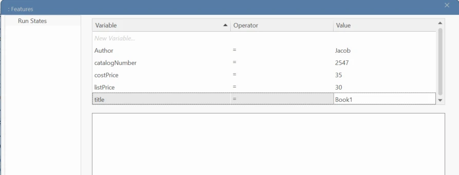
Each object box in this diagram reflects not only the relationships between objects (Account → Order → LineItem → StockItem), but also the specific values held by those objects at runtime. These include titles, authors, list prices, and item quantities.
By visualizing this information as an object diagram in UML, both developers and analysts gain clarity on how the system is behaving—not in theory, but in practice.
Here’s a quick guide to building an object diagram in software engineering using Sparx Systems Enterprise Architect:
Submit Your Request and We’ll Promptly Send a Payment link or Invoice.