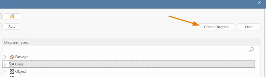
A UML Class Diagram is a visual representation of the structure of a system. It highlights the principle of building elements, which are referred to as classes, and their relationships with one another. Each class defines a type of object in the system, along with its properties and behaviors.
The class diagram’s value comes from how it helps in each stage of development. It serves as a domain model during the analysis phase, assisting in the transformation of real-world concepts into logical form. As you progress to the design phase, the process becomes increasingly technical as you establish the application architecture and data structures. In the future, the diagram can even be used as a template for the generation of actual source code during implementation.
Class diagrams are static, in contrast to those that emphasize process or flux. It does not characterize what occurs; rather, it describes the objects, their characteristics, and the connections between them.
Relationships are essential. For example:
In summary, a class diagram provides a structured, comprehensible representation of the system’s structure. It establishes the foundation for all that follows, improves communication among team members, and provides clarity to intricate systems when implemented effectively.
UML Class Diagrams is widely used in various domains like Software Engineering, Enterprise Architecture, Systems Engineering. Class Diagrams provide a diverse array of benefits, including the ability to design and maintain intricate systems. The following are a few of the considerable advantages:
Visualize the properties, relationships, and system components early in the design process.
Utilize object-oriented concepts such as inheritance and encapsulation to develop designs that are both modular and reusable.
Establish a common visual language to facilitate the alignment of technical and non-technical stakeholders.
With the help of powerful tools like Sparx Systems Enterprise Architect, you can generate or reverse-engineer code directly from the model.
Class diagrams act as dependable, comprehensible documentation for the purposes of development, auditing, and maintenance.
Unlock the full power of your architecture with modeling tools that can adapt. Buy Sparx EA Now!
UML Class Diagrams are made up of elements that represent the structural components of the system and connectors that establish relationships between them. The following is a categorized summary of these elements, as they are modeled and utilized in Enterprise Architect.
The structure, types, and specifications of a system model are determined by these fundamental components:
| UML Element Type | Icon in EA Toolbox | Description |
|---|---|---|
| Class |
|
A class is a representation of a specific type of object that reflects the structure and behavior of the object within the system. |
| Interface |
|
An interface establishes a contract or series of behaviors that implementing elements agree to conform, without giving the implementation itself. |
| Data Type |
|
A data type is a classifier that is similar to a class, but it is not capable of containing sub-data types. The value is the sole identifier of its instances. |
| Enumeration |
|
An Enumeration is a data type that is limited to a predetermined list of literals that the modeler has specified. |
| Primitive |
|
A Primitive element is a built-in data type that does not have an inherent structure, such as Boolean or Integer. |
| Signal |
|
Often employed to simulate triggers or events, a signal specifies asynchronous send requests that are exchanged between objects. |
| Association (n-ary) |
|
An n-ary Association is frequently employed in Class or Object Diagrams to represent intricate relationships that involve three or more elements. |
Connectors serve to illustrate structure, inheritance, implementation, and composition by describing the relationships between model elements.
| UML Connector Type | Icon in EA Toolbox | Description |
|---|---|---|
| Association |
|
An Association is a representation of a relationship between two elements, which is typically represented as an instance variable in one or both classes. |
| Generalization |
|
A Generalization connector defines an inheritance relationship, where one element inherits the features of another. |
| Composition |
|
Composition depicts a whole-part relationship in which the lifetime of the part is managed by the whole. If the whole element is deleted, the parts are also removed. |
| Aggregation |
|
Aggregation represents a shared ownership relationship where the part can exist independently of the whole. |
| Association Class |
|
An Association Class combines an association and a class, allowing the relationship itself to have attributes and operations. |
| Realization |

|
A Realization is used when the source element implements or fulfills the contract defined by the destination element, which is frequently an interface. |
| Template Binding |
|
Template Binding facilitates the reuse of generic structures with specific types by connecting a binding class to a parameterized class. |
These elements represent runtime roles, interfaces, and internal wiring within structured or composite classes.
| UML Connector Type | Icon in EA Toolbox | Description |
|---|---|---|
| Part |

|
A Part is a runtime instance of a class or interface and is used to show contained components within a composite structure. |
| Port |
|
A Port defines an interaction point between a classifier and its external environment and is useful for encapsulation. |
| Expose Interface |
|
The Expose Interface element graphically represents the interfaces that are either provided or required by a class, component, or part. |
| Assembly Connector |
|
An Assembly Connector links a required interface of one element with the provided interface of another, typically used in Component Diagrams. |
| Connector |
|
A Connector represents communication links between internal parts to illustrate how they collaborate to achieve the structure’s purpose. |
| Delegate Connector |
|
A Delegate Connector maps an external port to an internal implementation, showing how external behavior is supported internally. |
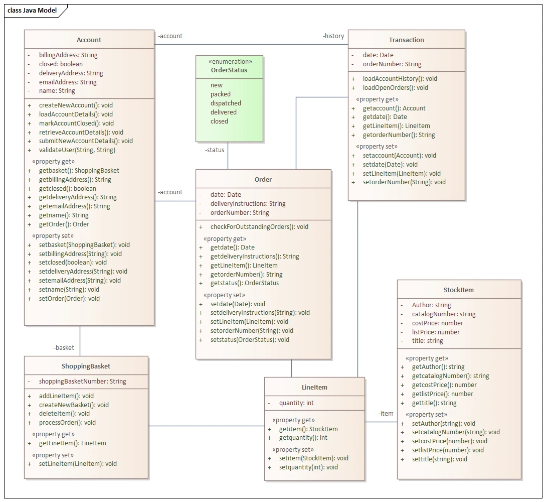
This structured representation of an Online Store Class Diagram in Sparx Systems Enterprise Architect provides a visual narrative of system architecture by demonstrating the interconnection of essential elements, including Account, Order, Transaction, ShoppingBasket, LineItem, and StockItem, through connectors such as associations and compositions.
The data and behavior of each class element are reflected in the attributes (e.g., billingAddress, orderNumber, quantity) and operations/methods (e.g., createNewAccount(), getLineItem(), setOrder()). The integration of property methods with Enterprise Architect’s sophisticated modeling capabilities facilitates real-world logic modeling and detailed encapsulation.
This diagram also includes an OrderStatus enumeration, which represents business states such as new, dispatched, or delivered, and their relationship to the Order class. This class model facilitates communication by utilizing precise connectors and an intuitive layout, which enables non-technical stakeholders to easily comprehend the system design.
Additionally, Sparx EA’s code engineering capabilities enable the direct conversion of this model into executable Java code, creating a seamless transition between design and implementation.
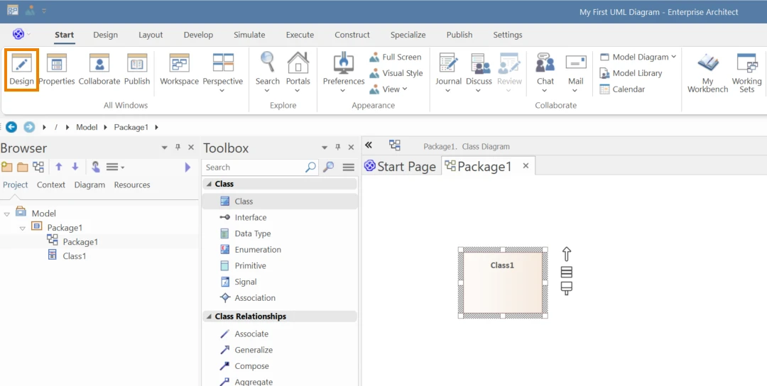
Open the Toolbox (Start > All Windows > Design) and drag & drop the required uml elements/connectors directly from the Toolbox.
Remember to Save (Ctrl + S) your work regularly.
Submit Your Request and We’ll Promptly Send a Payment link or Invoice.