Unified Modeling Language (UML) with
Sparx Systems Enterprise Architect
An Introduction to the Unified Modeling Language
The Unified Modeling Language, or UML, is a standardized visual language used to design and document software systems. It helps you create a map of everything, from high-level business processes to low-level code structures, all in a way that is easy to read and understand.
UML can be used to explain system functions, user interactions, database designs, or reusable components. But here’s the important part: UML is not a way to develop or process. It doesn’t matter if you’re using Agile method, the Rational Unified Process, or your own custom methodology; UML is just the language that brings structure and clarity.
UML gives you a standard technique to communicate ideas so that everyone on your team can understand what you’re trying to say, even if you’re modeling early ideas or developing the final architecture.
Create Your First UML Diagram in Enterprise Architect
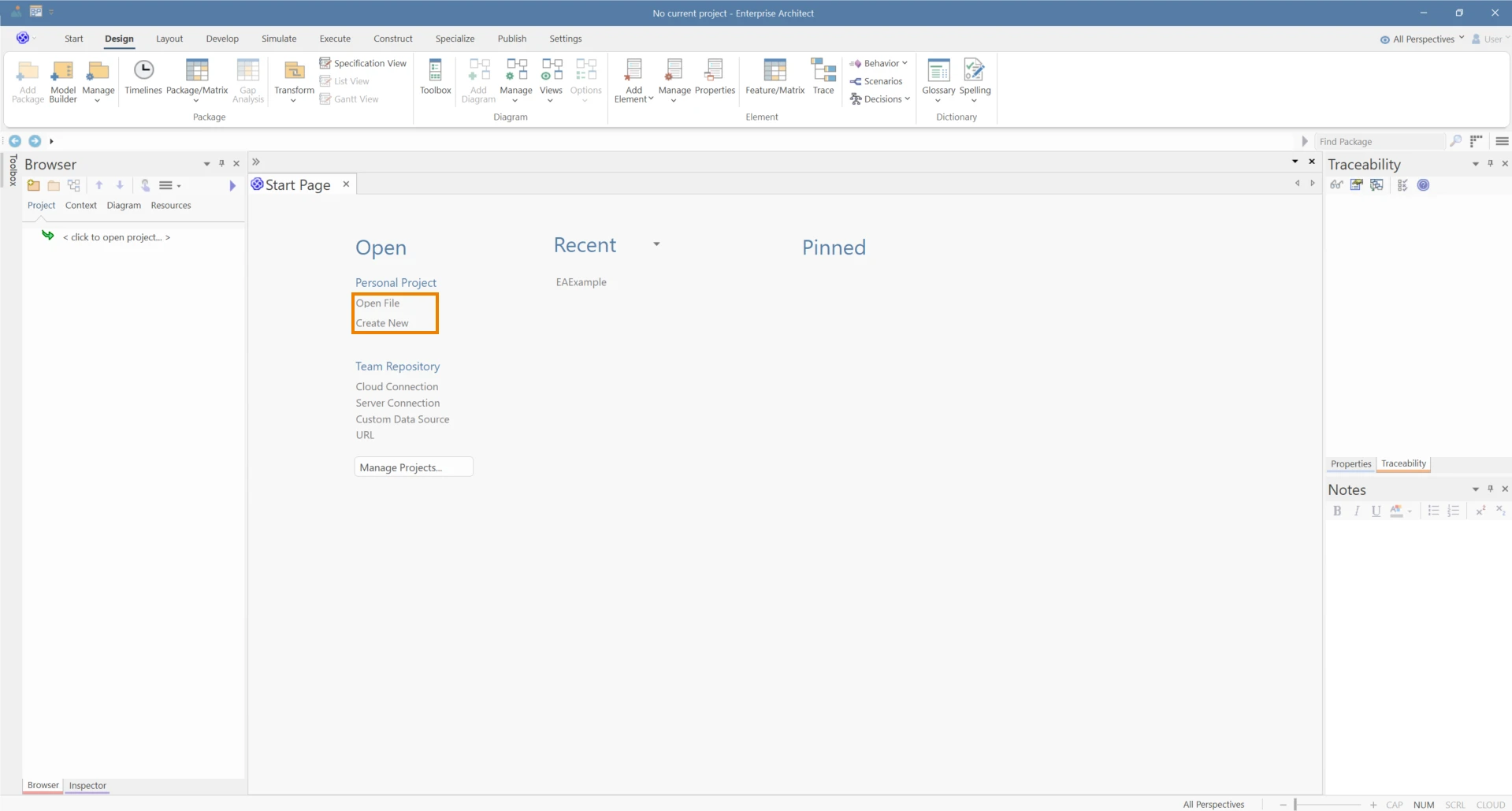
Open or Create a Project
Launch Enterprise Architect and open an existing project or create a new one. In the Project Browser, pick the package (or view) where you want to add your diagram.
Using Model Builder
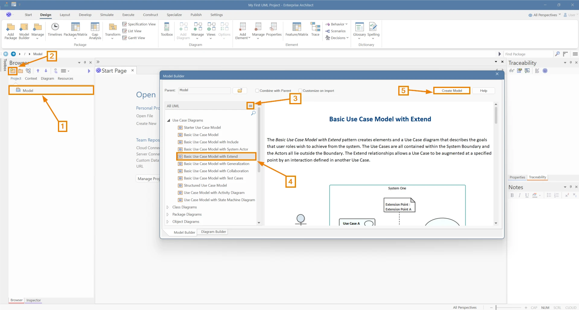
You can use built-in model patterns using the Model Builder and create UMLModel packages instantly:
Select the Root Node.
Click on the Model Builder icon in the Project Browser.
Click on the Perspective icon and select the UML > All UML or Structural or Behavioral Perspective.
Select a Model Pattern from the list of patterns shown.
Click on “Create Model”.
Using Diagram Builder
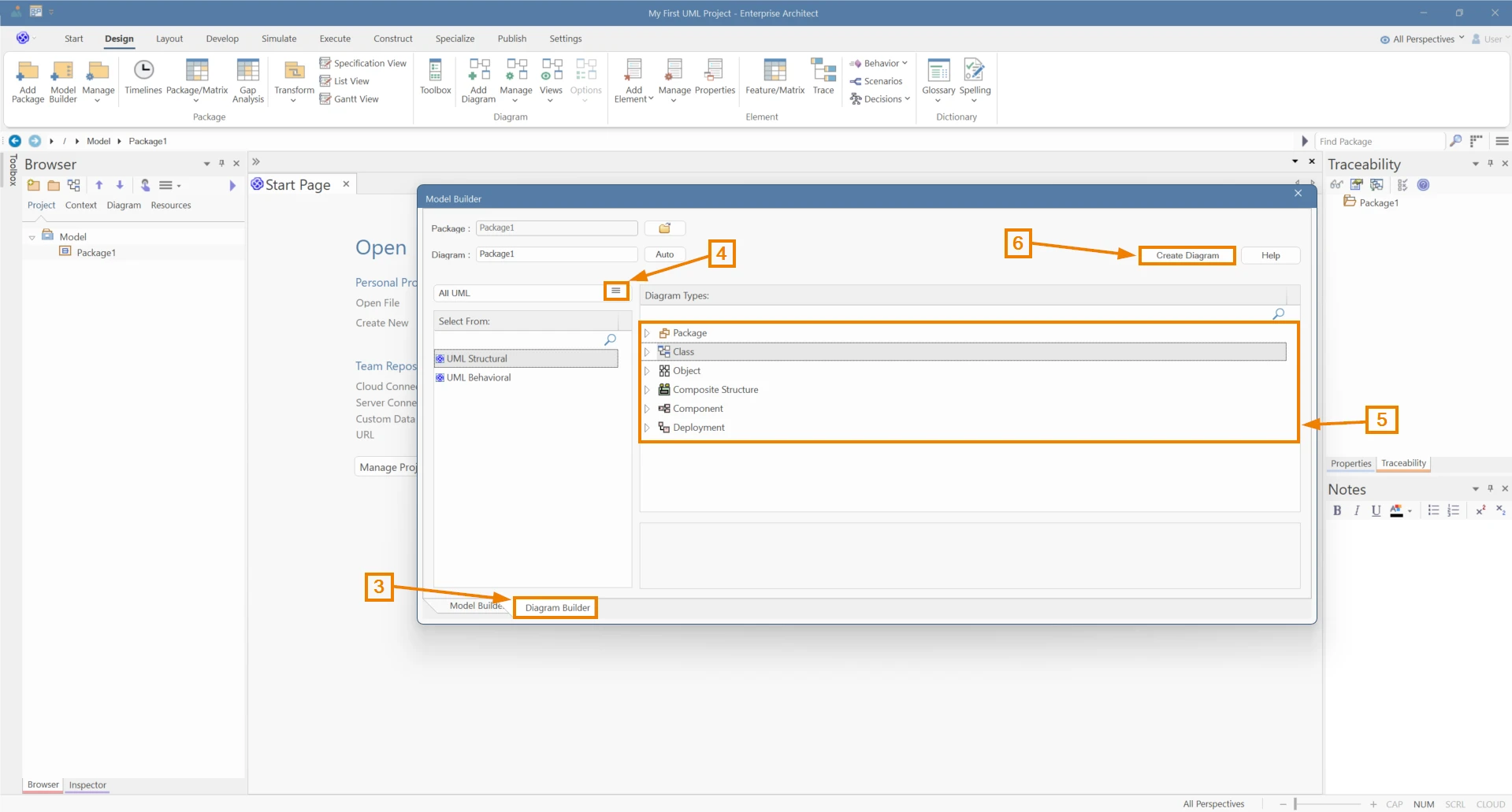
You can also use the Diagram Builder to create UMLDiagrams and build your model manually:
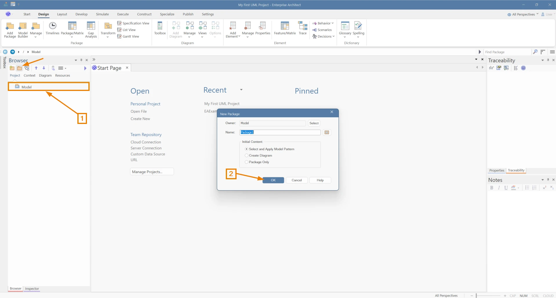
Select the Root Node
Create a Package for your Diagrams. As soon as you create the Package, the Model Builder will open automatically.
Switch to the Diagram Builder window.
Click on the Perspective icon and select the UML> All UMLor Structural or Behavioral Perspective.
Select the required diagram type
Click on “Create Diagram“.
Add elements with Toolbox
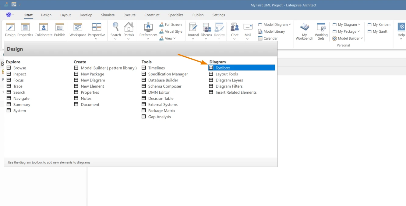
Navigate to the Ribbon > Design > Toolbox to enable the toolbox.
The Toolbox will show the appropriate elements and connectors for your diagram. You can change it anytime using the Perspective icon.
Drag UML elements like Classes, Actors and Use Cases with appropriate UML diagram relationships like associations, generalization or flows to define the required structure and behavior.
Refine and Save
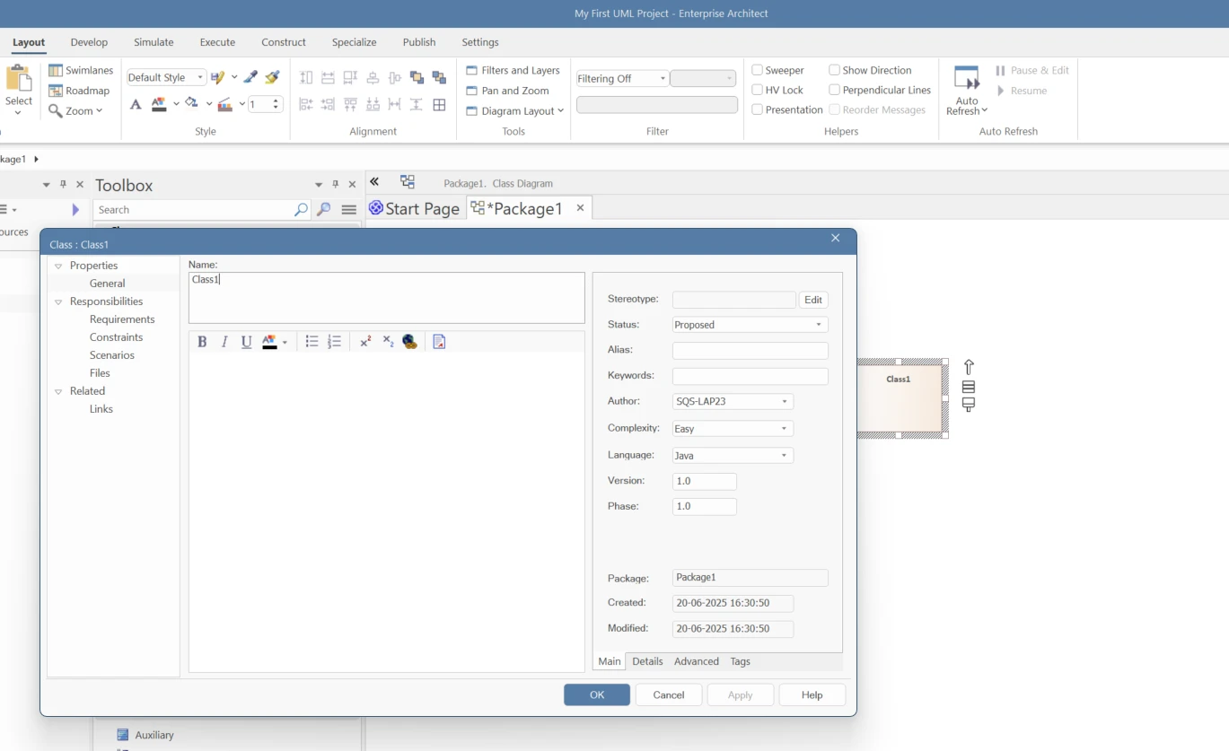
Double-click elements to set properties (attributes, operations, stereotypes, tagged values).
The Unified Modeling Language (UML) emerged in the early 1990s when object-oriented programming had grown popular to make software modeling more consistent. Grady Booch, James Rumbaugh, and Ivar Jacobson were three of the leading experts at the time, and they each had their own way of designing things.
Booch and Rumbaugh began merging their notations in 1995. At first, this was called the Unified Method. Jacobson shortly joined the team and added his work on use cases. The three friends, known as the “Three Amigos,” changed the name of their joint work to Unified Modeling Language (UML) to make it clear that it was a standardized visual language, not a development method.
Because their individual methods were so popular, UML quickly became accepted in the business world. Version 1.1 was sent to the Object Management Group (OMG) in 1997 and became an official standard. Later versions made improvements, and UML 2.0 in 2004 made big changes. The most recent version, UML 2.5.1, came out in 2017. You can learn more about the current specification through the official UML website.
UML is still the best way to visualize, document, and design complex software systems in many fields today.
Learn More
To learn more about the Sparx Systems Architecture Platform and Cloud Services from Sparx Systems North America
UMLmakes it easier to see how abstract ideas and complicated systems work. Encourages collaboration among developers and even helps stakeholders who aren’ttechnicalunderstand how the system works.
Picture Complex Code
Makes the software development process easier to understand by translating complicated lines of code into diagrams. It makes it easy to see how the different parts of a system interact and work together, saving a lot of time and confusion.
See The Bigger Picture
If you get stuck, it’s like having a blueprint right next to you that shows you what to do next. When you get lost in the details, UMLhelps you remember the bigger picture.
Helps Everyone Stay On The Same Page
UMLModels act as a single source of truth helping everyone on your team understand how the system is being planned and how it is moving forward, regardless of their role or stage in the development process.
Good for Non-Technical Meetings
Helps stakeholders, product owners, and managers understand how software works and what it can do. Helps teams work better by connecting stakeholders who are technical and those who aren’t.
Difficult to prove ROI or track delivery status?
Unify your architecture with tailored workflows. See Sparx EA Solutions in action.
Types of EA UML Diagrams
UML diagrams are broadly classified into the following categories:
Structural Diagrams
These diagrams illustrate the static aspects of a system – its architecture, components, and relationships. They do not capture changes over time.
They answer the question “What are the parts of the system and how are they related?”
Behavioral Diagrams
These diagrams capture the dynamic aspects – the interactions and changes within the system over time.
They answer the question “How does the system behave and interact in response to events or over time?”
Each type serves a distinct purpose in modeling various aspects of a system.
How Sparx EA Simplifies UML Modeling
Sparx Systems is a contributing member of the Object Management Group (OMG), actively participating in the improvement of UML. With years of expertise, Sparx Systems Enterprise Architect is by far the best UMLdiagram tool in the market, and it offers a comprehensive set of tools that help modelers build UML-compliant models across diverse standards.
Strong Support for UML Profiles and Metamodeling
You can import or build your own UMLProfiles—complete with stereotypes and tagged values—and simply drag them into your diagrams. Enterprise Architect helps you enforce domain-specific standards without fuss.
Seamless Code Engineering & Round‑Trip Sync
Generate and reverse-engineer code across languages like Java, C#, C++, Delphi, PHP, Python, and more. EA’s round-trip support keeps models and code aligned, cutting errors and wasted effort.
Simulation & Validation Made Easy
Run simulations for Activity, State, Sequence, BPMN/BPSim, and DMN models right inside EA. You can test logic flows, validate decision tables, and step through executions before writing a line of code.
Automated Documentation & Reporting
Pick a template and EA outputs diagrams, definitions, tagged values, and metadata in formats like RTF, HTML, or PDF. It’s all styled and snapshot-ready—ideal for stakeholder reviews.
Extensible Automation & Custom Rules
Want custom validation or diagram styles? Use SparxEA’s scripting and automation API to create reusable rules, style guides, or enforcement checks—perfect for keeping team-wide consistency.
Collaboration & Model Governance
Work with scoped repositories, version control, branches, or collaborate through Pro Cloud Server and Prolaborate integrations. EA manages access, change control, and dashboard views for teams.