UML Interaction Overview Diagram with Enterprise Architect

What is a UML Interaction Overview Diagram?

A UML Interaction Overview Diagram visualizes control flow by orchestrating other Interaction diagrams. It is a variant of the Activity Diagram, so common flow nodes—Start/End, Decision/Merge, and Fork/Join—behave the same. What changes is the content of the steps: instead of activity actions, you place two rectangular elements.

  • Interaction: an inline Interaction shown inside a rectangle; it can be a Sequence, Communication, Timing, or another Interaction Overview.
  • Interaction Occurrence: a reference to an existing Interaction diagram, rendered as a frame with ref in the title area and the diagram name inside. Create one by dragging an Interaction diagram from the Browser onto the overview; the frame reuses the original, it doesn’t copy it.

Use this diagram when you want a compact, flow‑first summary that ties multiple detailed scenarios together. In Sparx Systems Enterprise Architect, elements and connectors are available on the Interaction Overview pages of the Diagram Toolbox.

Benefits of the UML Interaction Overview Diagram

Interaction Overview diagrams help when you need a flow‑first summary that stitches together detailed scenarios. They reuse existing interactions, show branches and concurrency clearly, and keep large behaviors readable.

Orchestrates multiple interactions

Summarize end‑to‑end behavior by chaining Sequence, Communication, Timing, or nested Interaction Overview diagrams. Stakeholders see the path at a glance.

Reuse without duplication (Interaction Occurrence)

Reference, don’t copy. An Interaction Occurrence points to an existing diagram, so updates to the original flow are reflected in the overview—less rework, consistent results.

Clear branching and concurrency

Use familiar Decision/Merge and Fork/Join nodes (from Activity diagrams) to present alternatives and parallel subflows without redrawing messages.

Compact Executive View

Long message exchanges collapse into labeled frames, turning sprawling sequences into a page that fits design reviews and sign‑offs.

Easy drill‑down in Enterprise Architect

In Sparx Systems Enterprise Architect, each Interaction or Interaction Occurrence frame can open the referenced diagram for detail. This keeps the overview navigable while preserving traceability.

Start Your Training Journey Today!

Access our Beginner-friendly UML courses and step confidently into advanced Topics.

Basic Elements and Relationships in an Interaction Overview Diagram

Interaction Overview Diagram Toolbox Icons in Sparx EA

UML Element Type Icon in EA Toolbox Description
Diagram Frame diagram frame element in sparx ea uml interaction overview diagram A frame that references an Interaction diagram, used to place a scenario in context within the overview.
Interaction Occurrence interaction occurrence in sparx uml interaction overview toolbox A reference to an existing Interaction diagram, drawn as a frame with ref in the header and the diagram name inside. Used inline as an invocation of that interaction.
Control Flow control flow connector in enterprise architect uml interaction overview diagram A connector between nodes that models the progression of control from one step to the next.

Interaction Overview Diagram Connectors and Relationships

UML Connector Type Icon in EA Toolbox Description
Initial initial node in sparx enterprise architect uml interaction overview diagram Marks the entry point of the flow when the activity (overview) starts.
Decision decision node in ea uml interaction overview toolbox A branching point with guard conditions; flow continues on the path whose condition evaluates to true.
Merge merge node in sparx systems uml interaction overview toolbox Joins alternative paths back into a single flow.
Fork/Join fork join nodes in sparx uml interaction overview diagram Splits one incoming flow into multiple concurrent flows, joins multiple flows into one, or performs both in a single node.
Flow Final flow final node in enterprise architect interaction overview uml diagram Terminates a single path of execution without ending the entire activity.
Final final node in sparx systems enterprise architect uml interaction overview Indicates the completion of the activity; reaching it stops all remaining execution.

UML Interaction Overview Diagram Example

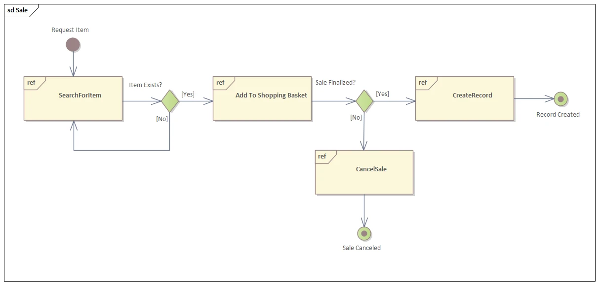
This UML Interaction Overview Diagram shows a compact, flow‑first view of a checkout. An Initial node (labeled Request Item) starts the control flow. The first Interaction Occurrence (ref) frame SearchForItem represents a reused interaction (an interaction use in UML terms). A Decision node Item Exists? splits the path:

  • [Yes] → Interaction Occurrence Add To Shopping Basket.
  • [No] → control loops back to SearchForItem (retry path).

After the basket step, a second Decision Sale Finalized? branches:

  • [Yes] → Interaction Occurrence CreateRecord → Final (Record Created).
  • [No] → Interaction Occurrence CancelSale → Flow Final (Sale Canceled).

This interaction overview diagram UML example emphasizes orchestration over message detail: reusable Interaction Occurrence frames summarize Sequence/Communication scenarios, while Control Flows, Decision/Merge, Final, and Flow Final nodes keep the logic readable. In Sparx Systems Enterprise Architect, this pattern lets reviewers drill down into each ref frame while keeping the end‑to‑end path on a single page—ideal when contrasting alternatives or presenting a interaction overview diagram vs activity diagram discussion.

How to Create a UML Interaction Overview Diagram in Sparx EA

Use these essential steps:

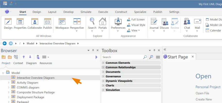
  • Select the Package in the Project Browser where the diagram will live.
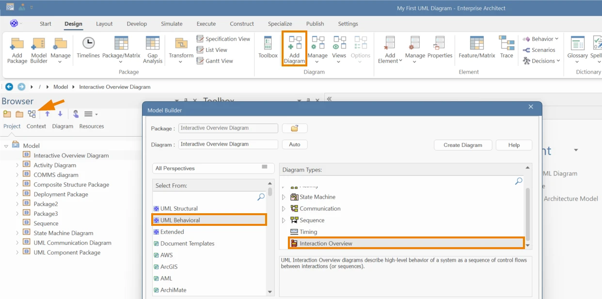
  • Go to Design → Diagram → Add Diagram and the create the interaction overview diagram by navigating to UML → Interaction → Interaction Overview.
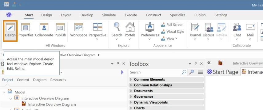
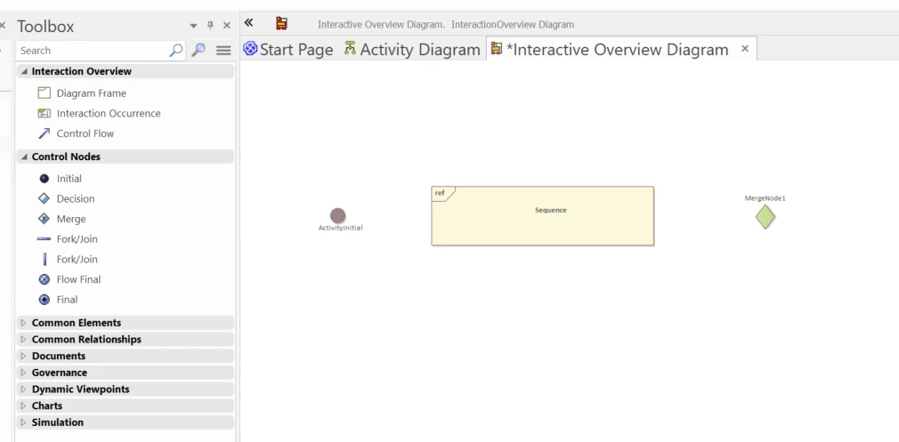
  • Open the Interaction Overview toolbox (typically auto‑opens; or Start → All Windows → Design → Toolbox).
  • Place nodes: Initial, Decision/Merge, Fork/Join, Final/Flow Final. Add Diagram and Interaction Occurrence (ref) frames where steps belong.
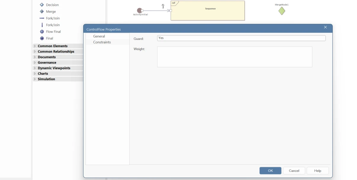
  • Connect the flow: connect nodes with Control Flow; add guard labels (e.g., [Yes], [No]) and keep a clear left‑to‑right path.
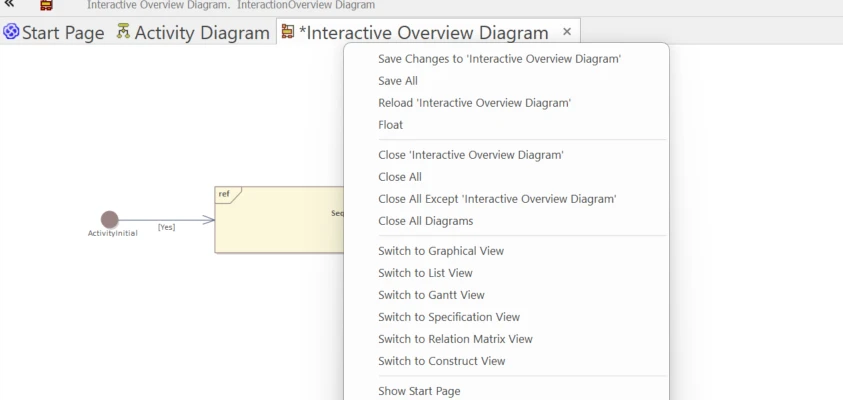
  • Save (Ctrl+S), then double‑click any Interaction/Occurrence to drill down and verify traceability.

Looking for Fast & Reliable Sparx EA Support?

Leverage our consultants’ expertise to align EA with your business goals. [Talk to a Consultant]

Learn More