UML Composite Structure Diagram with Enterprise Architect

What is a UML Composite Structure Diagram?

A UML Composite Structure Diagram shows the internal makeup of a classifier such as a class, component, or interface and how its parts collaborate to deliver the classifier’s behavior.

Instead of listing attributes and operations as a Class Diagram does, it opens the box and shows the pieces inside: parts (properties that reference a Class or Interface), ports (interaction points with the environment), and connectors (the wiring between parts or from a port to a part). Use it when you need to explain how responsibilities are distributed inside a design element, how messages travel through ports, and which internal pieces talk to each other. Introduced with UML 2, this view is especially handy in Sparx Systems Enterprise Architect for modeling internal structure and port‑based interactions on classes, components, and interfaces.

Benefits of the UML Composite Structure Diagram

Port‑based component design and clear contracts

Model provided/required interfaces on ports and wire them with assembly or delegation connectors. You get explicit contracts, cleaner boundaries, and fewer hidden dependencies—useful when teams split work across components.

Make internal responsibilities visible

Open up a class or component and show which parts do what, and how they collaborate. This reduces hand‑off friction and speeds up reviews because everyone can see the responsibilities, not just read them in prose.

Embedded/IoT designs that mirror real hardware

Represent sensors, controllers, and drivers as parts, with ports that map to pins or protocol endpoints. It’s easier to reason about signal flow and to show how an external device port is delegated to an internal driver.

Gateways, facades, and adapters inside services

Model how an external API port routes requests to validation, logging, and domain services. The diagram highlights coupling points and makes impact analysis straightforward when interfaces change.

Composable UI widgets and view models

Treat widgets as parts with event/command ports, then connect them to view models or controllers. This makes reuse obvious and gives testers clear seams for stubs and mocks.

Ready to Start Modeling Smarter?

Get Sparx Systems Enterprise Architect and begin creating powerful UML package diagrams with ease. Buy EA Now!

Basic Elements and Relationships in a Composite Structure Diagram

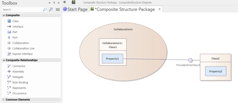
Composite Structure Diagram Toolbox Icons in Sparx EA

UML Element Type Icon in EA Toolbox Description
Class uml class element in ea toolbox Defines a type with state and behavior. In Composite Structure, a class can be a structured/encapsulated classifier that owns parts and ports.
Interface uml interface element in sparx ea toolbox A contract of operations or signals. In diagrams, ports show provided (lollipop) and required (socket) interfaces.
Part datatype element in uml ea tool A runtime slot inside a classifier, with a Class or Interface as its classifier.
Port datatype element in uml ea tool An interaction point on a classifier or part. Ports expose provided/required interfaces and route connections via assembly or delegation.
Collaboration datatype element in uml ea tool A reusable pattern of roles and their connectors that describes how participants work together.
Collaboration Use datatype element in uml ea tool Applies a Collaboration pattern in a specific classifier and binds roles to concrete parts.
Expose Interface datatype element in uml ea tool EA shorthand to display the required/supplied interfaces of a Class/Component/Part on Composite or Component diagrams.

Composite Structure Diagram Connectors and Relationships

UML Connector Type Icon in EA Toolbox Description
Connector uml associate connector A link between parts or ports. It may reference an Association to define its semantics and is used to satisfy required interfaces or convey signals.
Assembly uml generalization connector Connects a required interface to a provided interface—typically via ports—so internal parts can talk to each other.
Delegate uml compose connector Routes an external port on the whole classifier to an internal part’s port, exposing internal capability without tight coupling.
Role Binding uml compose connector In a Collaboration Use, maps each role in the pattern to the concrete part/classifier in this classifier.
Represents uml compose connector Indicates a classifier’s internal structure realizes (is based on) a Collaboration.
Occurrence uml compose connector Shows that a classifier is an occurrence/instance of a Collaboration pattern in this context.

Need Hands-On Training?

Accelerate your team’s modeling skills with our expert-led UML and Sparx EA training programs.

Online Book Store Example: UML Composite Structure in Enterprise Architect

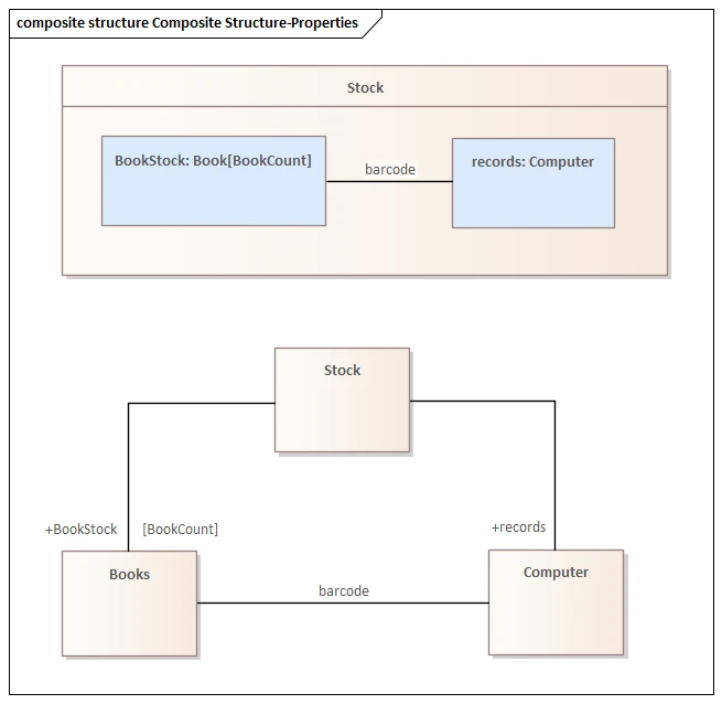
This UML Composite Structure Diagram Example of an Online Book Store made with Sparx EA shows a Stock classifier modeled as a composite with two internal parts:

  • BookStock: Book[BookCount] — a Part referencing the Book class. The multiplicity [BookCount] captures how many book instances are held at runtime.
  • records: Computer — a part that represents the system maintaining stock records.

An internal connector labeled barcode links BookStock and records. This expresses how each book instance is identified and looked up by the computer system during scans or updates. In other words, the connector models the operational path between physical stock and the record‑keeping component.

Below the composite, the Class Diagram presents the same idea at the type level: Stock is composed of Books (role BookStock, multiplicity [BookCount]) and associated with Computer (role records). The barcode association between Books and Computer is reflected as the internal connector in the composite view. Together, the two diagrams show who owns what (type relationships) and who collaborates at runtime (parts and connectors).

How to Create a UML Composite Structure Diagram in Sparx EA

Use the following steps to define a UML Composite Structure Diagram in Sparx Systems Enterprise Architect:

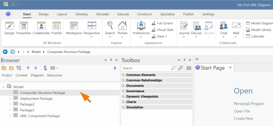
1. Select the Package in the Project Browser where the diagram should be created.

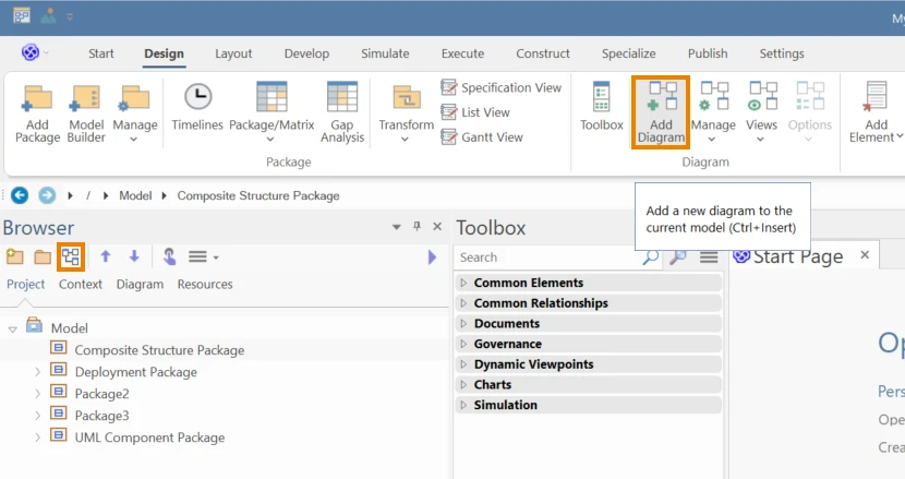
2. Go to Design > Diagram > Add Diagram, or click the Add Diagram icon above the Project Browser.

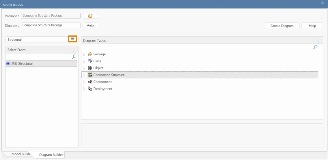
3. In the Diagram Builder, open the perspective icon, then UML > Structural, and choose Composite Structure.

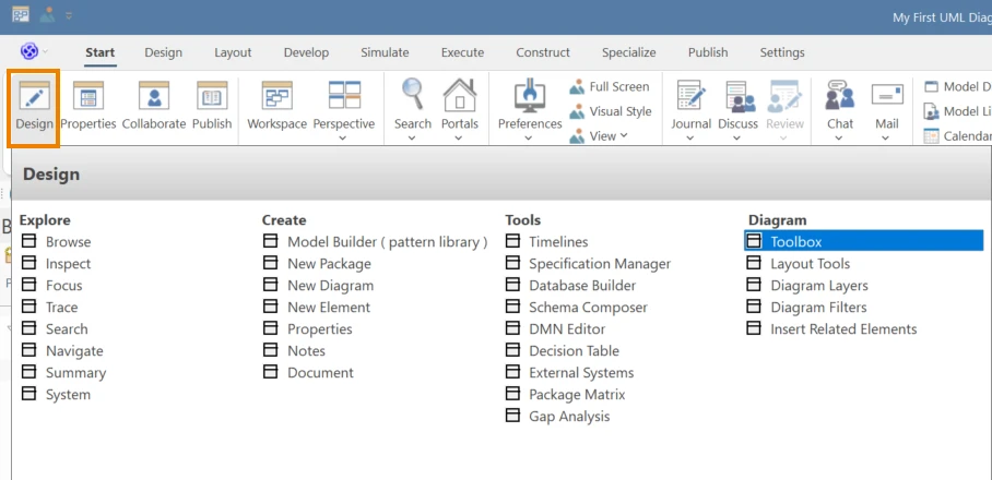
4. The Composite Structure toolbox opens automatically; or enable it via Start > All Windows > Design > Toolbox.

5. Drag and drop elements such as Class/Component, Part, Port, Interface, Collaboration, and Collaboration Use. Connect with Assembly or Delegation connectors; use Role Binding or Represents when applying collaboration patterns.

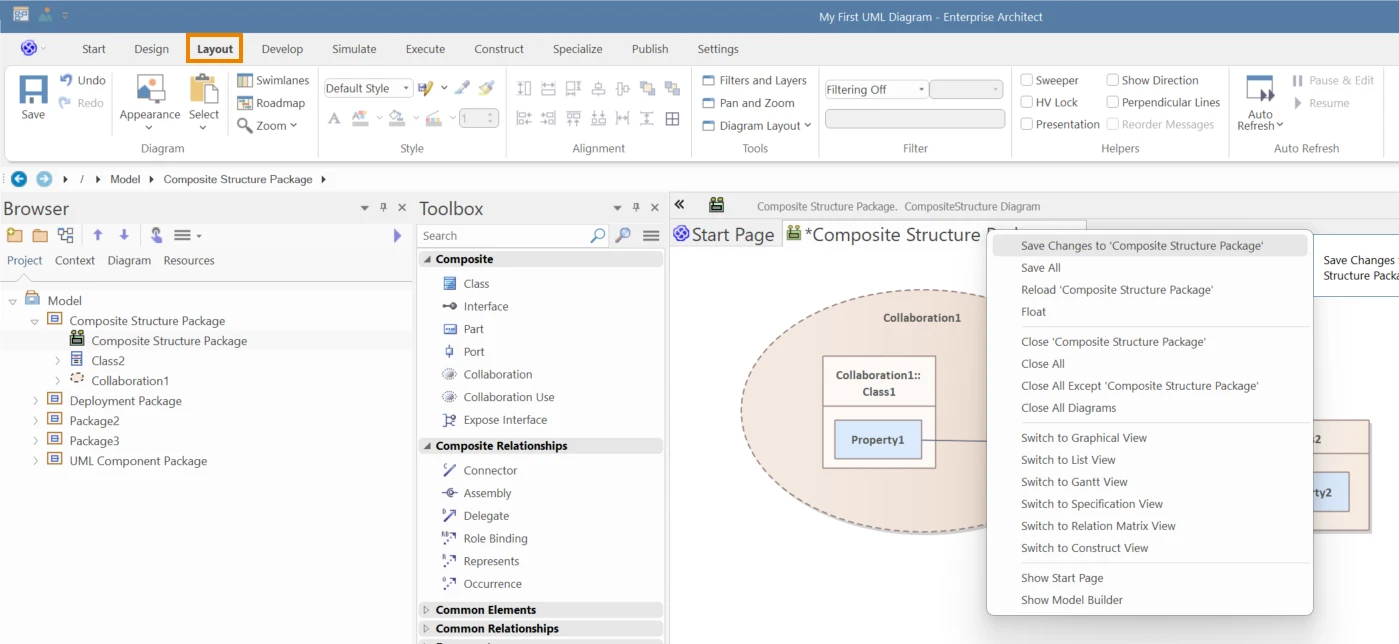
6. Save (Ctrl+S) regularly and use Layout tools and element Compartments (Ports, Parts) to keep the diagram readable.

Have a Complex Modeling Challenge?

Let our EA consultants help you structure, optimize, and scale your modeling efforts with precision. Talk to an EA Consultant now!

Learn More